Capacitors Description_Types, Uses & More
Introduction
Capacitors are one of the most basic and important components in electronic circuits. For engineers who design circuits, accurate acquisition of knowledge about the characteristics and properties of capacitors is essential for product development.
However, if you think about the basic operation and mechanism of a capacitor again, you may notice that there are some things that are overlooked or misunderstood.
For young circuit design engineers, we present the "You Cannot Ask About Now. Introduction to Capacitors" covering everything from the basics of capacitors to today's hot topic of large-capacitance capacitors.
Contents
- What Is a Capacitor
- Capacitors Function and Working
- Basic Properties of Capacitors
- Performance and Characteristics of a Capacitor
- Capacitance
- Withstand Voltage
- Dielectric Properties
- Resistance and Inductance
- Impedance
- Leakage Current
- Types and Construction of Capacitors
- Aluminum Electrolytic Capacitor
- Film Capacitor
- Ceramic Capacitor
- Electric Double-Layer Capacitor(EDLC)
- Features of Each Type of Capacitor
- Capacitor Selection
- Capacitor Failures
- For Large-Capacity Capacitors, Choose AIC Tech
- Conclusion
What Is a Capacitor
What role do capacitors play in electronic circuits?
This chapter explains the basic structure of capacitors, how they work, and the units used to express the size of capacitors in design and development.

Difference Between a Capacitor and a Condenser
There is no clearly defined difference between condensers and capacitors; both are electronic components that can physically store electric charges.
In English-speaking countries, it is called a capacitor because of its "capacity", but in Japan, it is said that it came to be called a "condenser" because it was translated as a "condenser (chikudenki)" because of its ability to condense electricity and store it.
What Is Capacitors Made Of
Key components that make up a capacitor include:
Electrodes (Plates):
Typically made of conductive metals such as aluminum, copper, or tantalum. These plates store electric charge when a voltage is applied across them.
Dielectric (Insulating Layer):
A non-conductive material placed between the electrodes that determines the capacitor’s characteristics. Common dielectric materials include ceramic, plastic film (polypropylene, polyester), oxide layers (in electrolytic types), or paper. The dielectric defines the capacitance value, voltage rating, and temperature stability.
Encapsulation (Sealing/Outer Case):
Made from resin, plastic, or metal housings, this protects the internal structure from moisture, heat, and mechanical stress, ensuring long-term reliability.
Capacitors Function and Working
In this section, we provide a clear, structured overview of the capacitor — exploring its construction, fundamental operating principles, and its essential functions within electronic circuits.
Structure
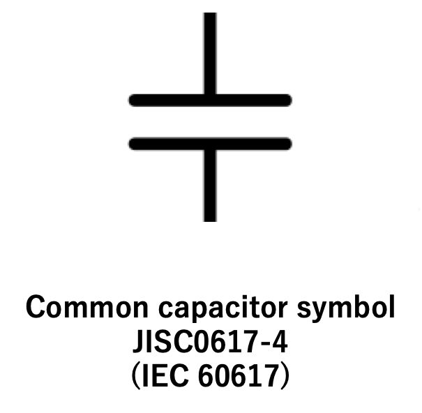
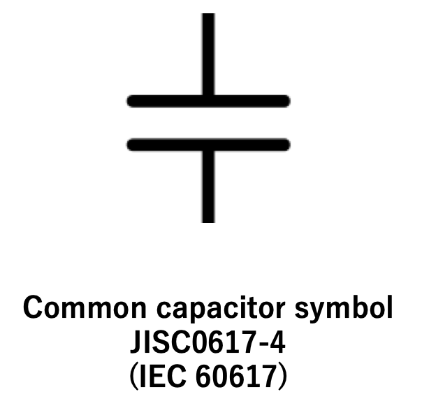
The circuit symbol used to represent a capacitor has two parallel lines drawn on it.
This indicates that the capacitor consists of two parallel conductor plate electrodes. For electrolytic capacitors with positive and negative polarities, the positive side may be marked with a + symbol. There are differences in notation methods among countries such as Japan (JIS), the United States (EIA), and Europe (EU, IEC).
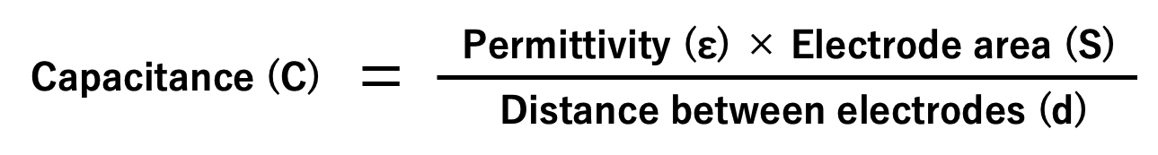
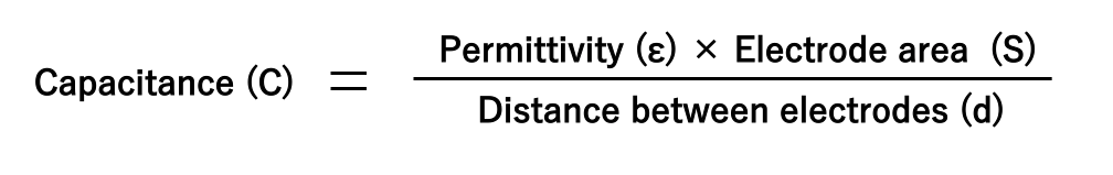
The larger the area of the capacitor's electrode plates and the closer the distance between the two electrode plates, the higher is its ability to store electricity.
In addition, the electrode plates are electrically separated by an insulating material. This insulating material gives the capacitor the ability (capacity) to interrupt the DC current and store electricity. These materials are commonly referred to as dielectrics.
Principle
As shown in the figure below, when the switch is turned on and a DC voltage is applied to the capacitor, electricity (electric charge) instantly accumulates on the electrode plate (b). If the voltage is removed, the electric charge accumulated on the electrode remains intact. (c).
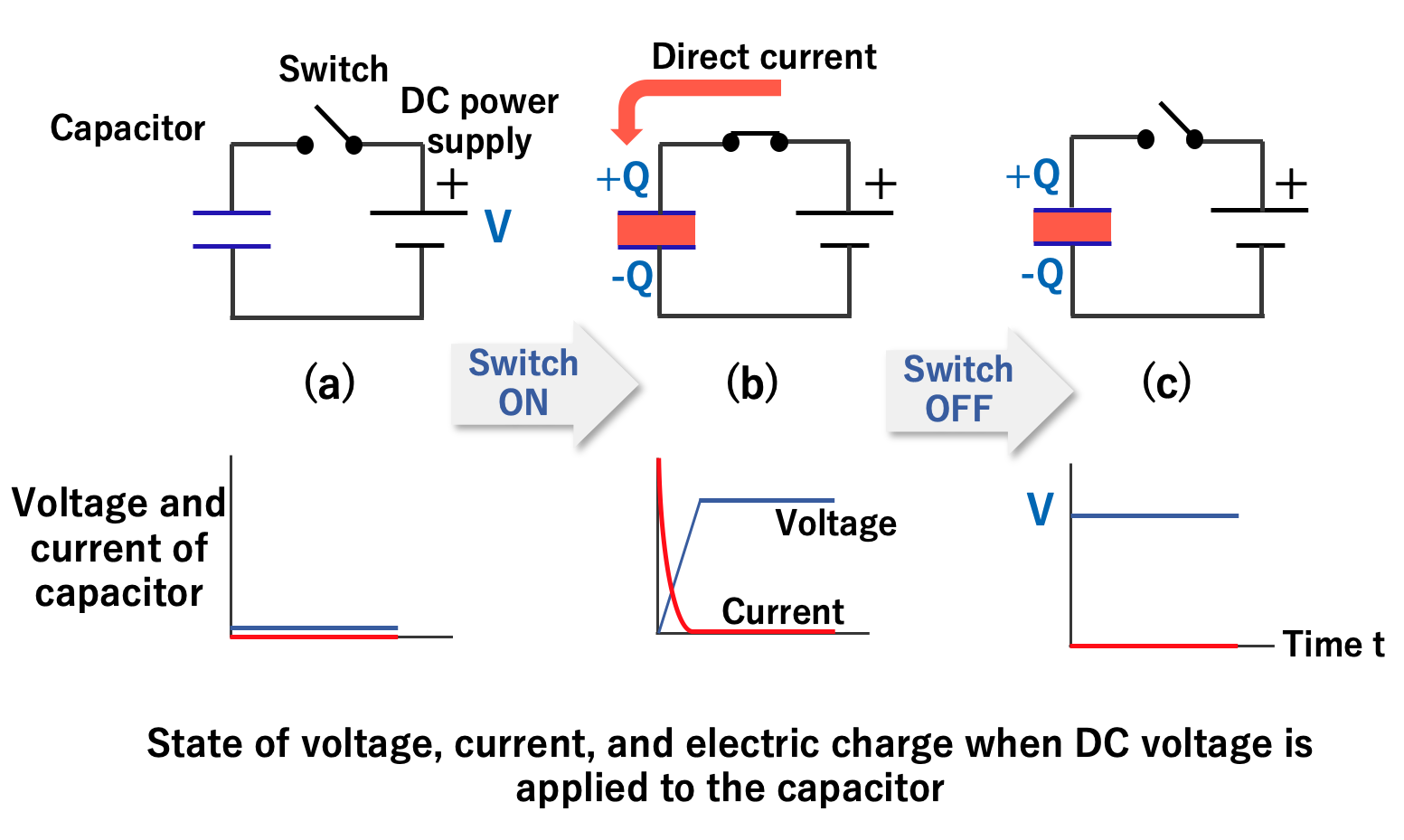
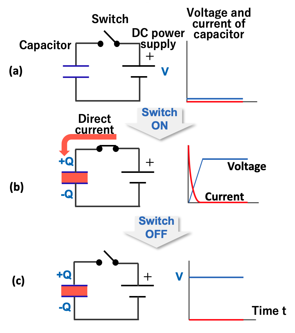
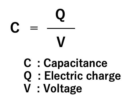
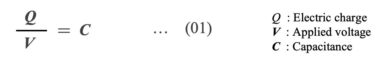
The ratio of the electric charge (Q) accumulated on the electrode to the applied voltage (V) is called the capacitance (C) of the capacitor. Capacitance is an index of the ability of an electrode to store an electric charge, and the unit called farad (abbreviated as F) is used in honor of the British physicist Michael Faraday. When a charge of one coulomb is stored on an electrode at a voltage of one volt, the capacitor is defined to have a capacitance of one farad.
As shown in the previous section, when a DC voltage is applied to a capacitor, an instantaneous electric charge accumulates on the electrode plate, and no further electric charge movement is possible.
In other words, the capacitor stops the DC current in an instant.
However, when an AC voltage is applied to the capacitor, the situation changes. This is because AC voltage is always switching between positive and negative voltage.
Initially, electric current flows like DC current, and an electric charge accumulates. However, when the voltage changes in the next instant, the accumulated electric charge is discharged. Then, the current flows in the opposite direction to the previous one to charge it.
In other words, charging and discharging are repeated in the capacitor according to the exchange of AC voltage, and it seems that electricity is flowing through it.
In summary, the functions of the capacitor are the following two:
① Stores the electrical energy, and give this energy again to the circuit when necessary.
② Blocks the DC current flow, and permits the AC current flow.
Also, the faster the alternating current voltage is switched (called alternating current with higher frequency), the easier it is for the capacitor to pass the alternating current.
Role in Circuits
Because of the above functions, capacitors perform two major functions in electronic circuits:
① In DC current, electricity is stored and discharged.
Capacitors not only store electric charge but also discharge it, so the capacitor itself becomes the power source. A simple example is the strobe light emission of a camera. The camera stores an electric charge in a capacitor built into the camera and discharges it all at once to create an intense flash.
② Create a clean direct current (remove AC components)
Using the function whereby the capacitor allows alternating current to pass through, it is possible to turn an unstable direct current with a wave-like component into a clean direct current.
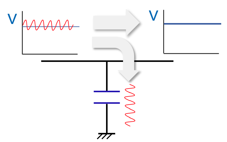
As shown in the figure, if a capacitor is connected between the input and output sides and connected to the ground, the AC component will flow to the capacitor and only the direct current will flow to the output circuit. It is also possible to output a stable voltage even if there is a large voltage wave at the input.
Capacitors in a circuit have a simple but very important function. Our capacitors are characterized by their small size, large capacitance, high withstand voltage, and long life. We will explain in detail how to use these characteristics in the next issue.
Basic Properties of Capacitors
A capacitor is a component that temporarily stores electrical energy. It blocks direct current (DC) while allowing alternating current (AC) to pass through by repeatedly charging and discharging. This section explains its fundamental purpose and operating principles.
Stores Electric Charge and Blocks DC
A capacitor is a device that stores electrostatic energy by accumulating electric charges on two closely spaced surfaces that are insulated from each other. A real capacitor is composed of an insulator sandwiched between two electrodes (Fig.1) .
When an insulator is placed between the electrodes of a parallel plate capacitor and a voltage V is applied, the insulator is exposed to the electric field E between the electrodes. Although the insulator blocks DC electric current to flow, the electric field causes the atoms of the insulator to split into positively charged and negatively charged parts*01 (Fig.2). In other words, an external electric field E (=V/d) induces an opposite induced electric field E’ in the insulator, and electrical energy is stored. This phenomenon is called dielectric polarization, and the material that causes dielectric polarization is called a dielectric.
*01 AIC Web-site: https://www.aictech-inc.com/information/capacitor_foundation03.html

Electric charges on electrodes

Electric charges on electrodes and in dielectric
As shown in Fig.3, the DC current flowing into a capacitor gets smaller over time. That is, initially, a large current flows into the capacitor instantaneously (charging current), and charge is stored in the electrodes. Subsequently, a current that polarizes the dielectric (absorption current) flows, causing dielectric polarization. Finally, when the capacitor is fully charged, no DC current flows *02 .

Capacitor voltage and current v.s. time
*02 AIC Web-site: https://www.aictech-inc.com/information/capacitor_foundation05.html
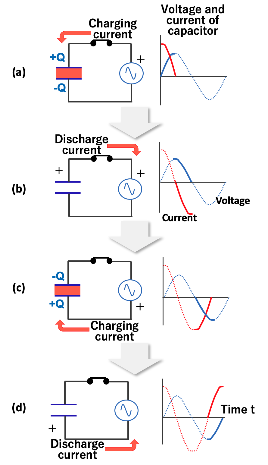
Allows AC to Pass
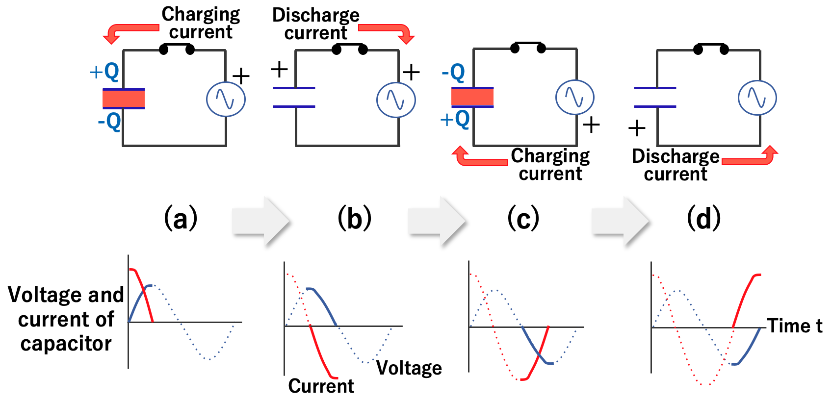
AC current flow periodically switches between positive and negative voltage. At first, the current flows from the positive pole of the power supply and charges the capacitor, just like direct current. When the voltage of the capacitor reaches the power supply voltage, V, the current goes to zero (Fig.4). As the power supply voltage drops toward zero, the capacitor discharges and current flows in the reverse direction (Fig.5).
")
AC current flow through a capacitor (charging phase)
")
AC current flow through a capacitor (discharging phase)
When the voltage reverses, the capacitor begins charging again, and the charging continues until the voltage reaches the opposite peak (Fig.6). Then, when the voltage tends toward zero, the capacitor begins to discharge and current flows in the opposite direction (Fig.7). In other words, in AC, the capacitor charges and discharges repeatedly as the voltage changes, and the capacitor behaves as if it made pass through AC current.
")
AC current flow through a capacitor (reverse charging phase)
")
AC current flow through a capacitor (reverse discharging phase)
Performance and Characteristics of a Capacitor
The performance and characteristics of a capacitor vary greatly depending on its dielectric material and structural design. In this section, we explain the fundamental parameters—including capacitance, voltage rating, dielectric properties, resistance and inductance, impedance, and leakage current.
Capacitance
The charge Q on a capacitor is proportional to the applied voltage V. Its proportionality constant is defined as capacitance C by Equation (01). In other words, capacitance is a physical quantity that expresses the ability of a capacitor to store an electric charge at an applied voltage.
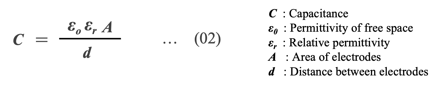
Capacitance C is expressed by Equation (02) using permittivity of free space ε0 (8.854×10⁻¹² [F/m]) , relative permittivity εr , area of electrodes A, and distance d between electrodes. Equation (02) indicates that the capacitance can be increased by using a dielectric with a large εr . Table 1 shows the relative dielectric constants of major dielectrics used in capacitors.
Withstand Voltage
The upper limit of the voltage that a capacitor can tolerate depends on the physical properties of the dielectric. That is, if excessive voltage is applied to the capacitor, the dielectric will not be able to block the DC current. This applied voltage is known as the breakdown voltage (VBD ) and is the product of the distance between the capacitor plates (d) and the dielectric strength (EDS ) *03 Equation (03) .
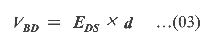
*03 F. T. Ulaby, Fundamentals of Applied Electromagnetics. Prentice Hall, 2007. [36]
As shown in Equation (02) and (03), VBD is proportional to d, while the capacitance is inversely proportional to d. Therefore, as the dielectric thickness increases, the maximum operation voltage increases, but the capacitance decreases.
To obtain a large capacitance, the electrode area A must be increased by using a dielectric with a large relative permittivity εr . Needless to say, this increases the physical size and hence the cost of the capacitor.
In real capacitors, various techniques and innovations are applied to economically and physically balance the trade-off between withstand voltage and capacitance.

*04 https://www.jstage.jst.go.jp/article/sfj/72/4/72_216/_pdf
*05 https://www.nature.com/articles/pj198470.pdf
*06 A. J. Moulson and J. M. Herbert, Electroceramics: Materials, Properties, Applications. John Wiley & Sons Inc, Jul. 2003. [32]
*07 T. Lebey, et al., “Origin of the colossal permittivity and possible applications of cct ceramics," in 55th Electronic Components and Technology Conference, 2005 (ECTC), 2005, pp. 1248-1253. [34]
*08 M. H. Yeh, Y. et al., “Electrical characteristics of barium titanate films prepared by laser ablation," Journal of Applied Physics, vol. 74, no. 3, pp. 2143{2145, 1993. [33]
The EDS value in Table 1 is as an ideal parallel-plate capacitor. However, real capacitor electrodes are not parallel plates, and dielectric breakdown occurs at sharp angles or points on the electrode surface rather than over the entire surface. Once the dielectric breaks down locally, the breakdown rapidly propagates from electrode to electrode, degrading the dielectric insulation and short-circuiting the capacitor*09.
Also, if a dielectric is stressed under very high electric field, the dielectric atoms ionize and the dielectric is destroyed *10. Furthermore, impurities and/or inhomogeneities in the dielectric can make the current flow more easily, and the dielectric can be destroyed at a lower voltage than the theoretical EDS value. If the dielectric is crystalline, the ionized atoms and free electrons by the high voltage can ionize other dielectric atoms, causing avalanche ionization*11.
*09 P. Scherz, Practical Electronics for Inventors. McGraw-Hill/Tab Electronics, Nov. 2006. [38]
*10 Intrinsic breakdown
*11 When excess conduction electrons flow through a solid with kinetic energy above a certain value, electron avalanche occurs, eventually breaking the bonds between the solids.
Dielectric Properties
The dielectric properties are major factor that characterize the performance of capacitors. Fig.8 presents the relative permittivity, continuous operational field strength and energy density limits of Al2O3, polypropylene and ceramics, which are the dielectric materials used in Al-Cap, MF-Cap and MLCC, respectively *12 . The theoretical limit is in the range of 10 J/cm3 and the commercial available one is about 2 J/cm3.
Al2O3 , the dielectric of Al-Ecap, has the highest energy density with high electric field strength and large dielectric constant. Ceramics may have a much higher dielectric constant than Al2O3 or plastic films, but they have a lower electric field strength, resulting in a volumetric energy density similar to that of film.
*12 M. Marz, A. Schletz, B. Eckardt, S. Egelkraut, and H. Rauh, “Power electronics system integration for electric and hybrid vehicles,” in Proc. Int. CIPS, 2010, pp. 1–10.

Relative permittivity, continuous operational field strength and energy density limits of various dielectric
Resistance and Inductance
An ideal capacitor has only capacitance; stored energy does not leak out of the capacitor and the charged energy is released without loss. In a real capacitor, however, there is not only pure capacitance C consisting of electrodes and dielectric, but also capacitance other than dielectric, resistance, and inductance. Also, since the dielectric is not a perfect insulator, a small leakage current (Ileak ) flows from the anode to the cathode during charging.
In an equivalent circuit, the leakage current is represented by a resistance Rp connected in parallel to the dielectric capacitance (C). The dielectric also has a dielectric absorption Cd and a dielectric loss Rd due to molecular polarization*13. In addition, there is an equivalent series resistance (ESR) due to the resistive component connected in series with the capacitance C, and an equivalent series inductance (ESL) is parasitic on the external terminals and internal lead tabs (Fig. 12).
In capacitor applications, it is necessary to know in advance that the various parameters of real capacitors will change under temperature, voltage, frequency, time, etc. This is because a more positive lifetime estimation is possible by taking into account the variation of each parameter with conditions.
*13 B. W. Williams, Principles and Elements of Power Electronics: Devices, Drivers, Applications, Passive Components. Glasgow, U.K.: Univ. Strathclyde, 2006, ch. 26. [4]

Equivalent circuit diagram of capacitor
Impedance
Impedance is an essential parameter in capacitors, representing their opposition to alternating current (AC) flow. It is determined by the combination of resistance (R), capacitive reactance (Xc), and inductive reactance (XL), and varies with frequency.
In capacitors, impedance decreases with increasing frequency up to a point, after which inductive effects cause it to rise. Key components influencing impedance include Equivalent Series Resistance (ESR) and Equivalent Series Inductance (ESL). ESR accounts for resistive losses, while ESL represents inductive properties inherent in the capacitor's construction.
Understanding these factors is essential for selecting capacitors that meet specific performance requirements in electronic circuits.

Leakage Current
Leakage current and insulation resistance are key parameters that describe a capacitor's insulation properties. For film and ceramic capacitors, which exhibit very low leakage current, insulation resistance (Riso) is the primary measure. In contrast, for aluminum electrolytic capacitors with higher leakage currents, leakage current (ileak) is used as the defining parameter.
These two properties are interconnected and can be expressed by a simple equation, highlighting their importance in evaluating a capacitor's performance and reliability.

Types and Construction of Capacitors
Although the basic role is the same, there are various types of capacitors depending on their application and size. This chapter explains the different types of capacitors and their respective characteristics.
Aluminum Electrolytic Capacitor
A capacitor that forms a dielectric oxide film on the surface of an aluminum foil that serves as the anode and uses an electrolyte or a conductive polymer, etc. as the cathode is called an aluminum electrolytic capacitor.
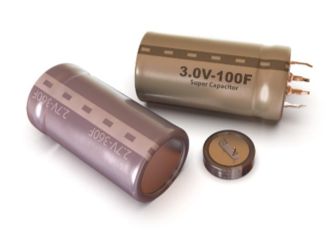
Many of them have a cylindrical shape and are so common that many people think of this shape when they think of capacitors. Compared to other types of capacitors, electrolytic capacitors have the major characteristic of being able to store a large amount of electricity even though they are the same size as other capacitors.
While most capacitors are made for digital circuits with a diameter of 10 mm or less, we sell products for power electronics circuits with a volume of 0.5 to 1 liter.
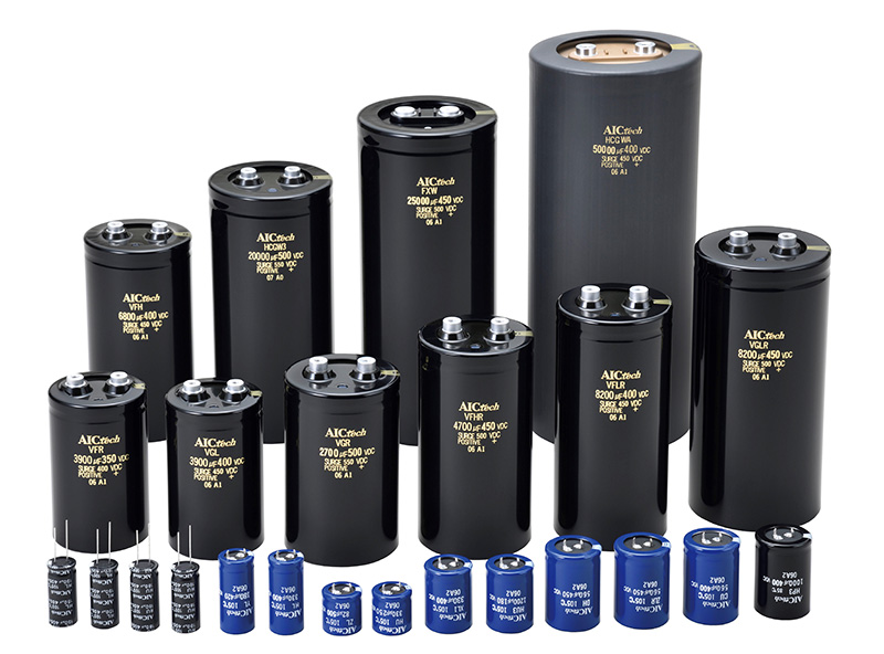
Aluminum electrolytic capacitors use an electrolytic solution filled in paper (separator), which has the disadvantage that the electrolytic solution evaporates with age and the performance deteriorates. They are consumable parts that need to be replaced periodically.
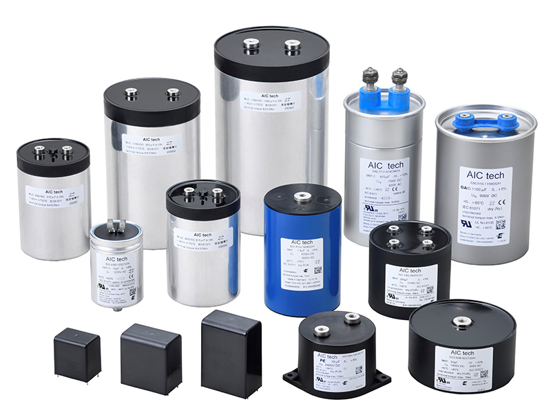
Film Capacitor
A film capacitor is a capacitor that uses plastic film as the dielectric. Compared to aluminum electrolytic capacitors, the amount of electricity stored in these capacitors is more stable at both high and low temperatures, and they can withstand higher voltages and have a longer service life.
Since the film is wound into a cylindrical shape to make the element, most of the products with large capacitance are cylindrical in shape, but square products are also made for small and medium capacity products. We have both types available.
For the film that becomes the dielectric, materials such as polypropylene used for food containers, syringes, DVD cases, etc., clothing fibers such as fleece, and PET (polyethylene terephthalate) used for beverage bottles are used. Since these materials have the ability to store electricity (permittivity), which is only about 1/4 that of aluminum electrolytic capacitors, in order to store more electricity, a large amount of film is required, resulting in a larger capacitor size.
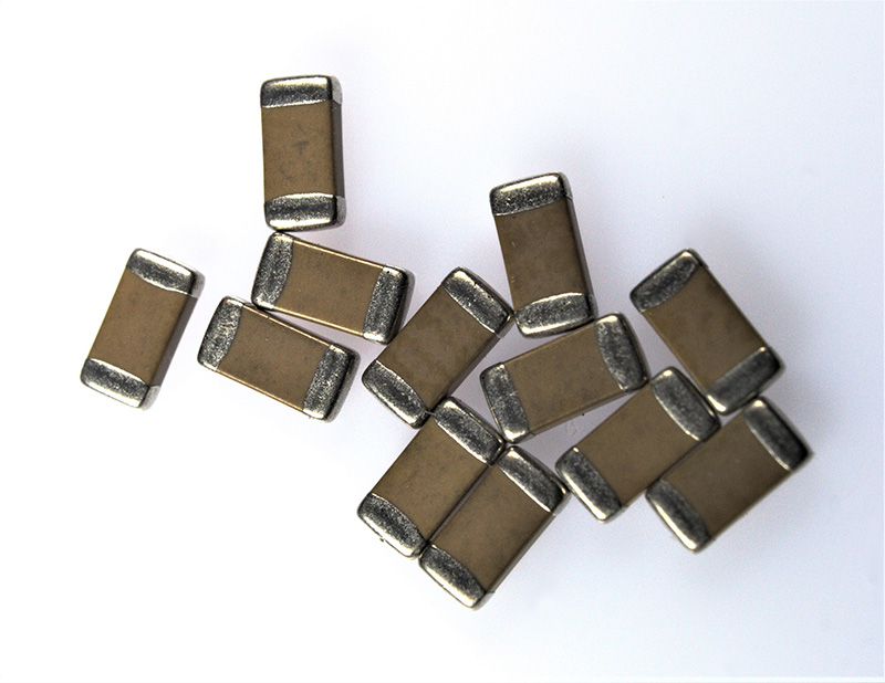
Ceramic Capacitor
A capacitor that uses ceramic (pottery) as its dielectric is a ceramic capacitor. By changing the composition of raw materials, it is possible to create dielectrics with various performances.
The electrodes are not rolled up like aluminum electrolytic capacitors or film capacitors but are fabricated by layering multiple layers of a compounded slurry-like ceramic material and paste-like electrode material. For this reason, small capacitors with a size of a few millimeters or less are generally used, and they play an active role in digital circuits. A single smartphone uses 800 to 1,000 ceramic capacitors, and the production quantity is the largest production volume among the capacitors.
Electric Double-Layer Capacitor(EDLC)
An electric double-layer capacitor has an extremely large capacitance compared to other capacitors. There is no dielectric in this capacitor, and a lot of electric charge can be stored in the area called the electric double layer, which is created between the activated carbon of the electrode and the electrolyte solution.
Since there is no dielectric to serve as the insulator as in other capacitors, the withstand voltage is low, and it is used as a power source like a battery rather than an electric circuit. Compared to rechargeable batteries, such as lithium-ion batteries, its characteristic is that the charging time is short.
Features of Each Type of Capacitor
Table 2 shows the overview and features of typical capacitor types. Capacitor types are classified by dielectric material, and as mentioned above, the dielectric has a significant impact on capacitance range, withstanding voltage, and other capacitor performance. However, even if the dielectric is the same, capacitors with different types of electrodes and element forms have different characteristics*14.
*14 AIC Web-site: https://www.aictech-inc.com/information/capacitor_foundation03.html

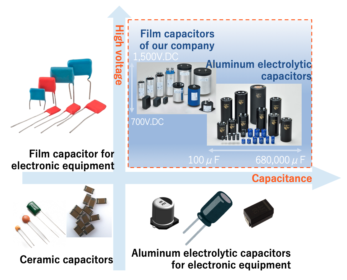
Rated Voltage and Capacitance Range
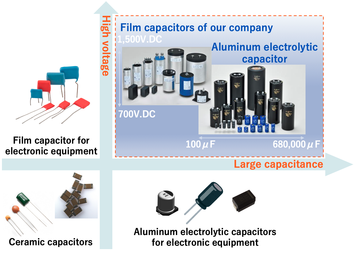
Fig.10 shows the range of capacitance and voltage rating covered by typical capacitors. Capacitors cover an extremely wide range of capacitance, from pico-Farad (pF, 10-12 Farad) to over 1 Farad (F). However, the range varies with the type of capacitor. In general, Al-Ecap covers the large capacitance range, but in recent years, MLCCs and MF-caps with large capacitance have been launched.

Range of capacitance and voltage rating covered by typical capacitors
The voltages range which a capacitor could cover depends on the capacitor type. Since the withstand voltage of a capacitor is affected not only by the type and thickness of the dielectric, but also by the material and structure of the electrodes, capacitor engineers conduct high-temperature load tests, evaluate insulation resistance, breakdown voltage, and electrical characteristics, and design voltage ratings based on these results.
The larger the margin between the voltage at which the capacitor is actually applied and the rated voltage, the higher the reliability. Equipment that requires higher reliability is often mandated to use a margin of 50% or less, and higher reliability can be achieved by using a margin of 50% or less.
Capacitors Uses and Application
In capacitor applications, the appropriate capacitor is chosen for the various functions and roles in the circuit. For example, the photoflash capacitor is used to store a large amount of energy, which can be released nearly instantaneously to power a xenon bulb, providing the light necessary for flash photography.
In this allocation, small sized AL-Ecaps are generally referred to as photoflash or strobe capacitors and several hundred microfarads with 300~450V rated voltages. On the other hand, Al-Ecap has a limited lifetime and larger ESR than other capacitors. Also, operational temperature range is relatively limited.
For this reason, Al-Ecap is not chosen for high-frequency filter circuits or applications where large ripple currents flow. In other words, there is a territory among capacitors by application as shown in Fig.11

Typical applications of Al-cap、MF-cap、MLCC and territories
Capacitors are integral components in various power conversion applications, each serving specific roles to ensure optimal performance and reliability. Here's an overview of their applications:
Motor Drives: Capacitors, particularly aluminum electrolytic types, are employed in motor drives to filter ripple currents and stabilize inverter operations. They act as energy buffers, ensuring smooth motor control across a range of applications, from household appliances to industrial machinery.
Renewable Energy Systems: In solar and wind power generation, capacitors function as DC link components, smoothing voltage fluctuations and enhancing power conversion efficiency. Their reliability is crucial for the long-term stability of renewable energy inverters.
Servo Drivers: These systems utilize capacitors to manage energy exchange during motor operations, ensuring precise control of speed and torque. Aluminum electrolytic capacitors are commonly used to filter high-frequency components and maintain stable inverter performance.
Switching Mode Power Supplies (SMPS): Capacitors in SMPS configurations filter input and output voltages, contributing to compact, efficient power supplies with low power consumption. They are essential for stabilizing voltage and reducing electromagnetic interference.
Pulsed Power Supplies: In applications requiring instantaneous high power, such as X-ray generators and welding machines, capacitors serve as energy buffers, delivering rapid energy discharge. Their capacitance directly influences the power supply's ability to generate high-energy pulses.
Uninterruptible Power Supplies (UPS): Capacitors in UPS systems provide immediate power during outages, bridging the gap until backup systems activate. They also filter voltage spikes, protecting sensitive equipment from power disturbances.
Traction Control Systems: In electric railcars and vehicles, capacitors manage energy flow within inverters, ensuring efficient motor control and braking. They handle significant ripple currents and voltage fluctuations inherent in traction applications.
For a more in-depth exploration of capacitor applications in power electronics, including detailed case studies and technical insights, visit AIC tech Inc.'s comprehensive article:
Capacitor Selection
To maximize the performance and reliability of electronic systems, selecting the most suitable capacitor for each application is essential. This section compares the characteristics of major capacitor types and outlines key factors to consider when choosing the right one.
Comparison Table
Selecting the appropriate capacitor type is crucial in power electronics, as it directly influences the performance, efficiency, and longevity of electronic systems. Each capacitor type—aluminum electrolytic, film, and ceramic—offers distinct characteristics that make them suitable for specific applications.

The table above summarizes the key characteristics of aluminum electrolytic, film, and ceramic capacitors, comparing parameters such as capacitance range, voltage rating, equivalent series resistance (ESR), high and low-temperature performance, energy density, and unit price. By presenting the strengths and limitations of each type, this table provides a clear reference for selecting the most suitable capacitor for specific applications.
Key Points for Selection
Key points to consider when choosing between aluminum electrolytic and film capacitors include:
Voltage Rating: Film capacitors handle higher voltages (up to several kV), while aluminum electrolytic capacitors are limited to around 600–700V.
Capacitance Stability: Film capacitors exhibit low capacitance variation with temperature and frequency, whereas aluminum electrolytic capacitors are more susceptible to changes.
Energy Density: Aluminum electrolytic capacitors offer higher energy density and are more compact, making them ideal for space-limited designs.
Ripple Current Handling: Film capacitors excel in ripple current rejection with low ESR, while aluminum electrolytic capacitors may require additional considerations.
Reliability: Film capacitors generally have longer lifespans and self-healing properties, while aluminum electrolytic capacitors require life calculations based on usage profiles.
Failure Modes: Film capacitors have better tolerance for overvoltage, while aluminum electrolytic capacitors are more prone to destructive failures under stress.
Cost: Aluminum electrolytic capacitors are more cost-effective upfront, but film capacitors may reduce additional circuit costs and offer greater long-term reliability.
Capacitor Failures
A capacitor is a critical component that underpins the reliability of electronic devices. However, depending on the operating environment and design conditions, it can experience failures or degradation. This section explains the primary causes and mechanisms of capacitor failures, as well as the key factors that influence their lifespan.
Causes of Failure
Capacitor failures can be categorized into two main types:
Catastrophic Failures: These involve a complete loss of function, such as open or short circuits. Such failures can lead to severe consequences, including enclosure explosions, smoke, ignition, harm to other electrical components, or leakage of liquid or gas from within the capacitor.
Degradation Failures: These are characterized by a decline in performance parameters, such as increased leakage current, elevated Equivalent Series Resistance (ESR), or reduced capacitance. The specific parameters and their acceptable limits can vary among manufacturers.
The failure mechanisms leading to these modes can differ based on the capacitor type:
Aluminum Electrolytic Capacitors (Al-Ecap): Common failure mechanisms include electrolyte evaporation, dielectric breakdown, and corrosion, which can result in increased ESR, reduced capacitance, or complete failure.
Metalized Film Capacitors (MF-cap): Failures often stem from dielectric degradation, electrode oxidation, or film delamination, leading to capacitance loss or open circuits.
Multilayer Ceramic Capacitors (MLCC): Susceptible to mechanical stress, thermal cycling, and dielectric breakdown, MLCCs may experience cracking, capacitance loss, or short circuits.
Understanding these failure modes and mechanisms is vital for selecting the appropriate capacitor type and implementing effective design strategies to enhance the reliability and longevity of electronic systems.
Estimated Lifetime
Estimating the lifetime of capacitors is essential for ensuring the reliability and longevity of electronic systems. The failure rate of capacitors typically follows a "bathtub curve," comprising three distinct phases:
Infant Mortality Phase: Characterized by a high initial failure rate due to manufacturing defects or early-life weaknesses.
Random Failure Phase: A period of relatively constant, low failure rates during the majority of the capacitor's operational life.
Wear-Out Phase: Marked by an increasing failure rate as the capacitor approaches the end of its useful life due to material degradation and other aging factors.
Key factors influencing capacitor lifespan include:
Operating Temperature: Elevated temperatures accelerate chemical reactions within the capacitor, leading to faster degradation.
Applied Voltage: Operating near or above the rated voltage can stress the dielectric material, reducing lifespan.
Ripple Current: High ripple currents generate additional heat, contributing to thermal stress and accelerated aging.
Manufacturers often provide lifetime estimation formulas that account for these variables, enabling engineers to predict capacitor longevity under specific operating conditions. By carefully considering these factors and selecting capacitors with appropriate ratings, designers can enhance the durability and performance of electronic systems.
Understanding common failure modes and their causes is crucial for effective troubleshooting and prevention. This article presents 15 practical case studies of capacitor failures across different applications, offering insights into identifying problems and implementing appropriate solutions.
Explore the full article below to enhance your knowledge of capacitor troubleshooting and ensure the longevity of your electronic systems.
For Large-Capacity Capacitors, Choose AIC Tech
In high-power circuits and industrial equipment, large-capacity capacitors are essential for storing energy stably and delivering it efficiently. This section introduces the fundamental structure and characteristics of large-capacity capacitors.
What Is a Large-Capacity Capacitor?
Although there is no clear definition of a large capacitance capacitor, we specialize in large capacitance capacitors for power electronics. So, what kind of capacitor is a large capacitance capacitor?
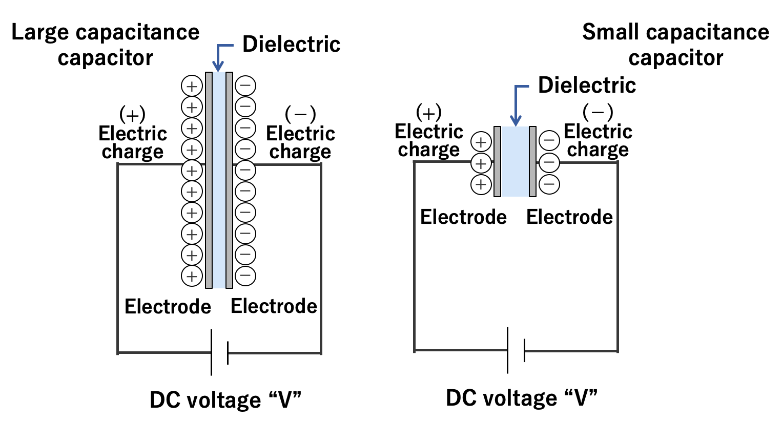
A capacitor stores an electric charge on an electrode. The larger the area of the electrode, the more electric charge can be stored. The two electrodes accumulate positive and negative electric charges, respectively, and the electric charges attract each other. The closer the electrodes are to each other, the stronger the force of attraction, so much electric charge is accumulated.
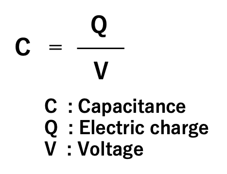
Also, as explained in section 1.2, an insulating material called dielectric is sandwiched between the electrode plates. Depending on the type of dielectric, the ability to store electric charge varies, and the index of that ability is called the permittivity. The above can be expressed in the following equation and diagram:
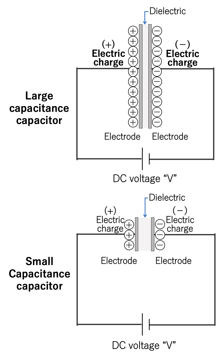
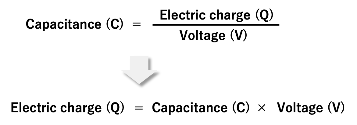
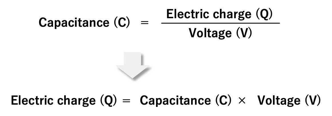
Also, as explained in section 1.2, the capacitance is the electric charge (Q) accumulated on the electrode divided by the applied voltage (V). If rewriting this equation, we can understand that as the voltage applied to the capacitor increases, the amount of electric charge increases.
Challenges of Large-Capacity Capacitors
Large-capacity capacitors face challenges in both miniaturization and compatibility with advanced power semiconductors.
Miniaturization
A large capacitance capacitor can be made by increasing the area of the electrodes and increasing the size of the capacitor. However, the use of large capacitors makes electronic devices larger and heavier, which leads to higher costs. For this reason, the miniaturization of large capacitance capacitors has always been a concern for customers and the most important task for capacitor manufacturers.
We have achieved the miniaturization of capacitors by improving electrode materials and processing technology. We are developing and improving materials and processing technologies, such as increasing the surface area of the anode aluminum electrode foil in aluminum electrolytic capacitors and using thinner films as dielectrics in film capacitors.
Coping with Evolving Power Semiconductors
In recent years, power semiconductors have evolved greatly in power electronics, where large capacitance capacitors are used, and devices have become more efficient and smaller. Capacitors for these applications are required not only to have a small size and large capacitance but also to have improved heat resistance and longer life.
In addition to the technologies we have cultivated in miniaturization, we are pursuing breakthroughs in large capacitance capacitors by developing electrolyte solution and film materials and improving the capacitors' structure.
Conclusion
Capacitors (C), along with resistors (R) and coils (L), are the three most essential passive components in electronic circuits. In electronic circuits, attention is focused on semiconductors, but without passive components, semiconductors would not work. In particular, capacitors are indispensable partners for semiconductors that operate on direct current.
This time, we have explained the basics of capacitors and their capacitance. We hope you have become familiar with capacitors.
As mentioned earlier, large capacitance capacitors include electric double-layer capacitors, aluminum electrolytic capacitors, and film capacitors, and we have a full lineup of all of these. However, the performance, size, and price of each large capacitance capacitor have advantages and disadvantages. For this reason, we offer solutions for your applications. Next time, we will explain the applications and reliability of capacitors. We hope you find this column useful.

Editorial supervision/Kazuyuki Iida
General Advisor, AIC tech Inc.
Born in the Tokyo area in 1956
M.S. of Sc, Sophia University, Tokyo, Japan. 1982
Over 35 years experience with knowledge on capacitor technology, i.e. R&D for high-performance capacitor and its materials, marketing activities at Hitachi Chemical Co, Ltd. and Hitachi AIC Inc. and Contributed articles on capacitors to public relations magazines, trade journals, and various handbooks.
Instructor of capacitor technology at the Technical Training Institute of Hitachi, Ltd. from 2005 to 2015.
General advisor to AIC tech Inc. from 2020.
- "Tantalum Electrolytic Capacitor"
The Electrochemical Society of Japan (ed.) Maruzen Handbook of Electrochemistry, 5th Edition, Chapter 15, Capacitors, Section 15.2.4 b (1998) - "Development Trend and Material Technology of Tantalum-Niobium Capacitors"
Technical Information Association of Japan Seminar June 2008 - Lead-Free Surface Mount Film Capacitors MMX-EC, MML-EC Series
Hitachi Chemical Technical ReportNo. 48. Product Introduction 2007 - "Film Capacitors for Electronic Devices"
Maruzen Capacitor Handbook, 5th Edition, Chapter 5, Film Capacitors, Section 5.2 (2009). - "Film capacitor MLC series for new energy"
Shinkobe Electric Co., Ltd. Shinkobe Technical Report Np. 22 (2012).
PDF Download