Capacitor Capacitance Explained:
Definitions, Factors, and Applications
Introduction
A capacitor stores electric charge when a voltage is applied, and its ability to do so is defined as capacitance.
This article explains the basic principles behind capacitance using the parallel-plate model and electric fields, then introduces how dielectrics increase capacitance, how units and symbols are handled, and how capacitance changes with temperature and frequency. It provides a clear, concise overview of how capacitors work and the practical characteristics that define their performance.
Contents
CAPACITANCE
- Definition of Capacitance
- Relationship between Capacitance and Dielectrics
- Units and Symbol Rules for Capacitance
- What you should keep in mind about capacitance
- Nominal capacitance CN and tolerance
- Capacitance versus Temperature
- Capacitance versus Frequency
- Capacitance deterioration over time
- Capacitance of Aluminum Electrolytic Capacitors
- Capacitance Summary
Definition of Capacitance
When conductive plates such as metals are placed parallel to each other in a vacuum and a voltage is applied, different and equal amounts of electric charge Q accumulate on the plates. At this time, an electric field is created in the space between the plates (Figure 1) *01 ,*02
The magnitude of this electric field, E, is expressed by (01) as the quotient of the voltage V applied between the plates and the distance d between the plates.

Electric charge Q and electric field strength E

*01 Electric charge is the amount of electricity a charged object has. More electrons compared to protons equals and less electrons equals +. The symbol is Q and the unit is expressed in C (coulomb).
*02 An Electric field can be considered an electric property associated with each point in the space where a charge is present in any form. It is represented by a vector because of its magnitude and direction. An electric field is also described as the electric force per unit charge. Electric fields are usually caused by varying magnetic fields or electric charges. Electric field strength is measured in the SI unit volt per meter (V/m).
The electric field can be thought of as a vector of lines of electric force, which emanate from a positive charge and go toward a negative charge, and the flat plate emits lines of electric force of Q / ε0 [lines] *03 . Since the area density of the lines of electric force is equal to the magnitude of the electric field, if the area of the flat plate is S [m2], the relationship is as in Equation (02), and the charge Q on the flat plate accumulated by the power supply is expressed in Equation (03), indicating that the parallel plate has the function of storing electric charge.
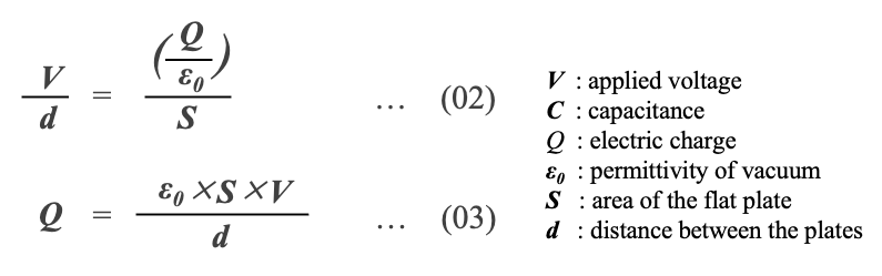
*03 This is an equation based on Gauss's law. Gauss's law is one of Maxwell's equations. In a medium with dielectric constant ε, the number of lines of electric force perpendicular to a closed surface is proportional to the total amount of electric charge Q in the closed surface and is equal to Q/ε
https://physnotes.jp/em/gauss-law/
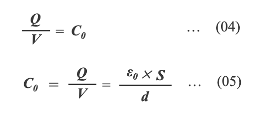
The value obtained by dividing the charge Q by the applied voltage V indicates the amount of charge per unit voltage (Equation (04)) *04, and this value is called capacitance as a physical quantity that indicates the ability to store an electric charge. The capacitance C0 of a parallel plate capacitor in a vacuum is expressed by Equation (05).
*04 The relationship between charge Q, voltage V, and capacitance C can be shown by the following triangle
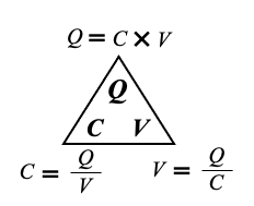
The relationship between the charge Q, voltage V, and capacitance C can be explained by imagining the capacitor as a water tank (tank). This is called "Water Tank Analogy." In Figure 1-02, the water storage capacity W of a tank is the product of the tank's bottom area S and the water level h. Considering the water storage volume as an electric charge and the water level as a voltage, the capacitance can be interpreted as the bottom area of the tank, Equations (06, 07). That is, the stored charge Q is proportional to the voltage V, and its proportionality constant is the capacitance C.

Water Tank Analogy
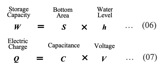
- Capacitance is a physical quantity that the ability to store an electric charge.
- The stored charge Q is proportional to the voltage V, and its proportionality constant is the capacitance C.
TIPS
When an external charge dQ applied to a capacitor, its terminal voltage rises (dV) and energy dU is stored in the capacitor. If the voltage is V when the capacitor is charged until the charge reaches Q, the energy U stored in the capacitor can be expressed as the product of voltage and charge using equation (08). This is illustrated in Figure 3.
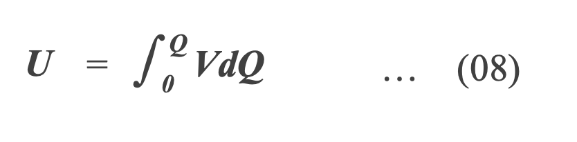

Charge versus voltage
Using equation(07), dQ can be expressed as equation(09). So, the energy stored in a capacitor is proportional to its capacitance and the square of voltage(equation(10)).
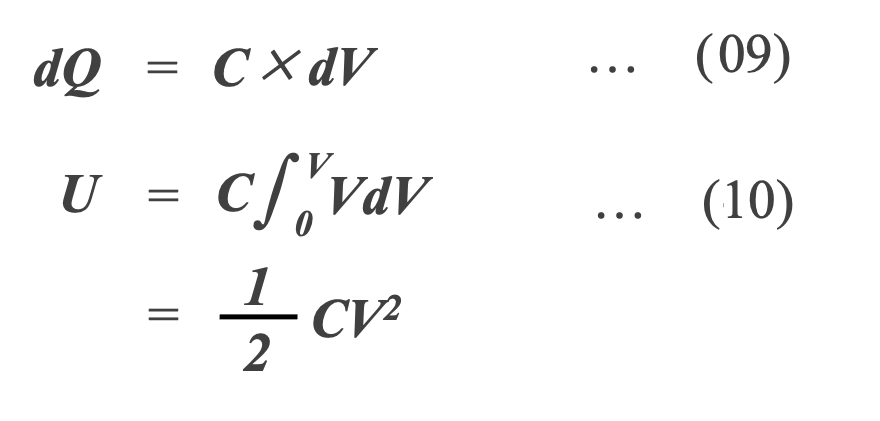

Energy stored in a capacitor
Relationship between Capacitance and Dielectrics
A real capacitor has an insulator called a "dielectric," and the properties of the dielectric affect many of the characteristics of the capacitor.
Dielectric and dielectric polarization
When an insulator is placed between the electrodes of a parallel plate capacitor and a voltage V is applied, the insulator is exposed to the electric field between the electrodes.
Although no current flows when voltage is applied to the insulator, the electric field causes the atoms of the insulator to separate into positively charged and negatively charged parts*05 (Figure 05).
In other words, an external electric field E (=V/d) induces an electric field in the insulator that is opposite to the external electric field, and electrical energy is stored. This phenomenon is called dielectric polarization, and the induced electric field is called the induced electric field (E').

Dielectric polarization*05
*05 An external electric field orients the electrons in the atoms and molecules of an insulator in the opposite direction of the external electric field.
As a result, the insulator's charge is biased negatively on the side opposite to the direction of the electric field and positively on the side in the direction of the electric field. The biased charge throughout the insulator creates an electric field within the insulator.
The efficacy of dielectric
The voltage V between the electrodes becomes smaller because the external electric field is weakened by the induced electric field. When electric charge is supplied from the power supply to maintain the strength of the electric field at V/d until the voltage between the electrodes, which has become smaller, is restored to the original voltage, more electric charge accumulates on the electrodes. In other words, by inserting a dielectric between the electrodes, more charge can be stored at the same voltage.
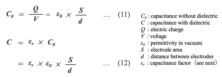
The capacitance C0 of a capacitor without dielectric is expressed as Equation (11), but if we consider that the charge stored by the dielectric is increased by a factor of εr , the capacitance C of a capacitor with dielectric is given by Equation (12).
Types of dielectrics*06
The "εr" discussed in the previous section is a dimensionless value called relative permittivity. The larger the dielectric with a larger εr , the larger the capacitance of the capacitor. Table 1 shows the types of dielectrics used in major capacitors.

*06 Dielectrics are broadly classified into two types.(1) Non-polar typeWhen an electric field is applied to a dielectric, the electrons in the dielectric are displaced relative to the atomic nucleus, inducing a dipole and storing an electric charge.(2) Polarization typeWhen an electric field is applied to a dielectric with dipoles in random directions in advance, the dipoles align and store electric charge.Air, gases, polystyrene, etc. are non-polar dielectrics, while metal oxides, which are dielectrics for ceramics and electrolytic capacitors, are polar dielectrics.
*07 Simizu et.al., Journal of the Surface Finishing Society of Japan 72 (4) , 2021 https://www.jstage.jst.go.jp/article/sfj/72/4/72_216/_pdf
*08 The temperature characteristics of ceramic capacitors are attributed to the type of dielectric ceramic. Class-1 is a non-ferroelectric ceramic based on titanium dioxide and has excellent temperature stability due to its paraelectricity. Class-2 is ferroelectric, usually based on barium titanate. It has a very high dielectric constant compared to Class-1.
- A dielectric is an insulator in which an external electric field causes charge orientation and polarization.
- Dielectric has the function of increasing the capacitance of a capacitor.
- The coefficient by which a dielectric increases its capacitance is the relative permittivity.
TIPS
When there is a vacuum between the electrodes, charge is stored only at the electrodes. Its ability to store charge is expressed as the dielectric constant ε0 of a vacuum as follows in Equation (13) *09 . This constant indicates that if two electrodes with an area of 1 cm2 are at a distance of 1 cm and there is a vacuum between the electrodes, their capacitance is 0.0854 pF.
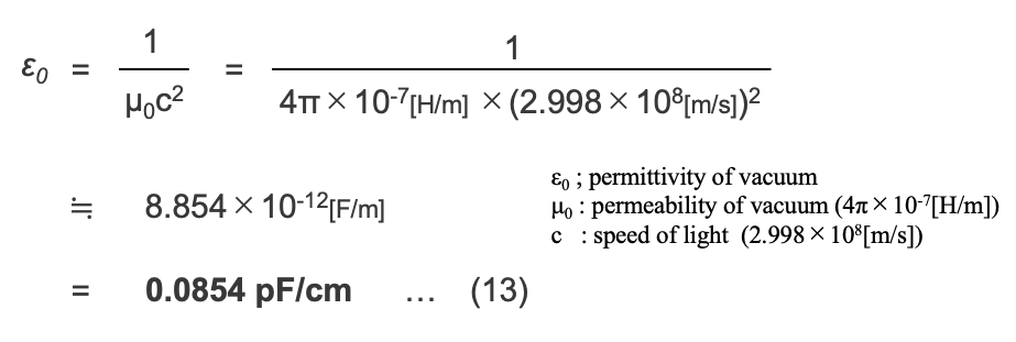
*09 Dielectric constant is a physical quantity that describes the response of a dielectric material to an electric field. However, since a vacuum is not a dielectric, the dielectric constant of a vacuum is not a dielectric constant that represents a physical property.
Units and Symbols Rules
Unit and Prefix
The unit of capacitance is the farad (abbreviated as F), named after the British physicist Michael Faraday*10. A capacitor with 1 farad stores 1 coulomb of charge at a voltage of 1 volt. That is, 1F = 1Q/V. However, since the capacitance of capacitors used in actual circuits is much smaller than 1 farad, the three prefixes µ (micro), n (nano), and p (pico) are usually used (Table 2).

*10 The "Faraday," a unit of electric charge, is also derived from Michael Faraday.
Rules
The rated capacitance of capacitors is specified according to the E series of IEC. Generally, the E3 series or E6 series shown in Table 3 are often used.
The "E" in E series stands for exponent, and in the case of the E6 series, the value of 6√(10n) (the sixth power root of the nth power of 10) in the definition formula, where n is six numbers from 0 to 5, is used for the capacitance. In addition to E3, E6, and E12 shown in Table 3, there are E24, E48, E96, and E192.
Since each series is related to the capacitance tolerance, the E6 series is used for capacitors with ±20% tolerance, such as electrolytic capacitors, and the E12 series is used for capacitors with a required ±10% tolerance.

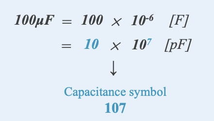
In order to represent a variety of capacitance values, there is a rule that combines two digits of the capacitance value with a multiplier; this rule, based on pF (pico farad), is common to all capacitors. For example, the symbol for 100μF is determined as follows.
10μF can be rewritten as 100×10-6F. Rewriting this using the prefix p(10-12) yields 10 × 107pF. The multiplier "7" is combined with the first digit "1" and the second digit "0" to obtain "107". This is the capacitance symbol for 100μF*11.
For capacitance of 100pF or less, read the displayed number as it is. Note, however, that there are two symbols for 100pF: "101" and "100". For a capacitance of less than 10pF, "R" is used as the decimal point. 2.2pF is written as "2R2".
*11 Since 1000 μF is 1000 × 10-6 F, when expressed using the prefix p, the multiplier is "8," so "108" is the capacitance symbol. In the case of 47 µF, the symbol is "476", 4.7μF is "475", and 0.47μF is "474". The larger figure at the end means the larger the capacitance.
- Usually, μF or pF is used as the unit of capacitance.
- In order to represent various capacitance values, a common capacitance symbol is used for each capacitor.
TIPS
What are the senses of scale of 1 coulomb [C] and 1 farad[F]?
According to Coulomb's law, the electrostatic force F acting on a positive point charge of 1 [C] and a negative point charge of 1 [C] at a distance of 1 [m] is about 10 billion newtons[N], equivalent to the force to lift a heavy object of about 1 million tons*12 (Figure 6).

Charge and electrostatic force
The amount of electricity generated by a lightning strike is said to be 0.2 to 20 [C] for summer lightning and 3.5 to 3,000 [C] for winter lightning*13 .Thus, 1 coulomb is an impossible amount of electricity in a normal circuit, and capacitors with a capacitance of 1 [F] are rarely used in actual circuits, except in some power equipment*14.
*12 https://hegtel.com/coulomb.html This force is equivalent to the thrust of a large rocket.
*13 https://www.jstage.jst.go.jp/article/jwea1977/31/4/31_4_98/_pdf Takada et. al., JAPAN WIND ENERGY ASSOCIATION 38 (4) 98 2007
*14 Some electric double-layer capacitors (EDLCs) have capacities in excess of 1F. However, EDLCs have no dielectric and store electrical energy by physically adsorbing ions in the electrolyte on the surface layer of the electrodes.
What you should keep in mind about capacitance
Capacitors cover an extremely wide range of capacitance from pF (pF, 10-12 farads) to 1 farad (Figure 7). In general, aluminum electrolytic capacitors cover the large capacitance range, but in recent years, ceramic capacitors and film capacitors also have products with large capacitance in the 1mF (1000μF) class (Figure 7).

Major capacitor types and capacitance range
Nominal capacitance CN and tolerance
The nominal capacitance CN is a design value. The capacitance shown on the capacitor body is the nominal value, not the actual. There is a difference between the actual capacitance value*15 and the nominal, which is called the tolerance. The tolerance is usually expressed as a percentage deviation from the nominal value and can be set in the range from -20% to +80%(Table 4).
If a capacitor with a nominal capacitance of 100 μF has a tolerance of ±20%, its actual capacitance is guaranteed to be between 80 μF and 120 μF.
Generally, capacitors with tolerances of "J (±5%)", "K (±10%)", and "M (±20%)" are used. Film capacitors, mica capacitors, and class 1 type ceramic capacitors are also available with smaller tolerances (higher capacitance accuracy). However, for capacitors with extremely small capacitance, the tolerance is sometimes expressed as a value, such as 10pF±1pF.

*15 The measurement method is specified in JIS C 5101- 1:2019 (IEC 60384-1:2016) Section 4.7, including frequency, measurement voltage (Vrms), and temperature.
Capacitance versus Temperature
Capacitance varies with temperature. This is due to the temperature characteristics of the dielectric and the structure of the electrodes, and the magnitude of capacitance change depends on the type of capacitor. Temperature compensated ceramic capacitors and film capacitors show a small change in temperature (Figures 8 and 9), but ceramic capacitors of high dielectric constant system and aluminum electrolytic capacitors using electrolytic solution show a very large change in temperature, so bypass circuits that are relatively insensitive to the magnitude of capacitance change, Therefore, they are used in bypass circuits and decoupling circuits, which are relatively insensitive to the magnitude of capacitance change.

Temperature compensated ceramic capacitors*16, 17
C0G : 0±30ppm/℃
U2J : -750±120ppm/℃

Metalized film capacitor*18
PP : polypropylene
PET : polyethylene terephthalate
*16 https://www.doeeet.com/content/eee-components/passives/class-1-ceramic-dielectrics/
*17 C0G and U2J are EIA code. Their JIS code are CG, U2J , UJ, repectively.
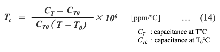
[Temperature coefficient TC for Class 1 ceramic and film capacitors]
When capacitance changes almost linearly with temperature as shown in Figure 8, the slope of the capacitance change with respect to temperature is called the temperature coefficient (TC), which is defined by the equation 14. Specifically, the capacitance change when the temperature changes by 1°C from the reference temperature T0*19 is expressed in units of parts per million (ppm/°C).
*19 The reference temperature differs between JIS and EIA standards: 20°C for JIS and 20°C for EIA.
Temperature coefficients are used in Class 1 temperature compensated ceramic and film capacitors (Tables 5 and 6). A positive temperature coefficient means that the capacitance increases as the temperature rises. A negative temperature coefficient is used when the capacitance decreases with increasing temperature.


*20 G. Sitaramaraju et al., Electical Characteristics Of Metallized Polypropylene Film Capacitor With General Technical Data - Comparative Study, International Journal of Engineering Research & Technology (IJERT) Vol. 2 Issue 4, April - 2013
[Capacitance change of Class 2 ceramic and electrolytic capacitors]
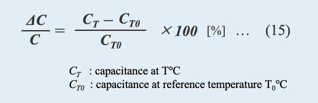
In ceramic capacitors of high dielectric constant type and aluminum electrolytic capacitors, capacitance varies nonlinearly with temperature (Figure 10). In those cases, the characteristics are expressed using the capacitance change ratio defined by Equation (15).
 and Aluminum electrolytic capacitors")
Capacitance change ratio versus temperature,
Ceramic capacitors of high dielectric constant type(X5R, Y5V)*21, *22,
and Aluminum electrolytic capacitors*23, *24
*21 https://www.eeweb.com/multi-layer-ceramic-capacitors-mlcc/
*22 X5R : EIA code, Capacitor change within ±15% at -55~ Y5V : EIA code, Capacitor change within +22~-82% at -30~+85℃ range
*23 AICtech's type HL snap-in capacitor 500V 560μF
*24 20℃ as reference temperature
Capacitance versus Frequency
The higher frequency, the smaller capacitance. This is because the dielectric constant becomes smaller under high frequencies. As mentioned in section 1.2, a capacitor can store an electric charge when an external electric field causes polarization in the dielectric. However, it takes time to polarize. In alternating electric field, where the electric field reverses periodically, the polarization and relaxation are repeated. In low frequency alternative field (e.g., 50Hz or 60Hz alternating current for household use), the polarization barely can catch up with the electric field changes, so the dielectric constant does not decrease much and capacitance does not decline*25 .
*25 At DC voltage, it polarizes instantaneously in less than a nanosecond.
However, when the electric field changes 1 million times per second (1 MHz) or hundreds of millions of times per second (in the radio frequency range), the polarization cannot keep up with the changes in the electric field, and the field reverses before a perfect polarization state is reached. As a result, the dielectric constant becomes smaller (Figure 11).

Schematic diagram of permittivity versus frequency *26
*26 http://www.ieice-hbkb.org/ Dielectrics are made up of components that have different responses to frequency, and therefore different possible frequencies. Therefore, the permittivity is frequency dependent.
The magnitude of the capacitance decrease also depends on the electrodes and structure of the capacitor. In general, ceramic and film capacitors with metal electrodes have a small capacitance change, while aluminum electrolytic capacitors with electrolyte have a larger change (Figures 12 and 13).

Capacitance versus frequency of metalized film capacitor

Capacitance versus frequency of aluminum electrolytic capacitor
Capacitance deterioration over time
Capacitance may decrease over a long period of time when capacitors are used. For this reason, each capacitor has a specified capacitance change rate for various life tests. For our screw terminal type aluminum electrolytic capacitors, we guarantee that the capacitance change will be within ±15% of the initial value when the rated voltage is applied for the specified time *27 under the atmosphere of upper category temperature (Figure 14). The change in capacitance over time is due to the decrease in electrolyte and increase in conductivity caused by temperature and voltage.
The metalized film capacitors have the self-healing action *28. It causes the metalized electrode to evaporate, reducing the surface area of the electrode and lowering the capacitance.

Capacitance change at ripple charged life test of our aluminum capacitors
A : Type FXW 400V30000μF (ΔC/C < ±15% @5000h ,85℃ (1))
B : Type VGLR 450V 6800μF (ΔC/C < ±15% @5000h ,105℃ (1))
C : Type HCGW 450V32000μF (ΔC/C < ±15% @2000h, 85℃ (2))
*27 Capacitors are tested at DC voltage or ripple voltage superimposed on DC voltage in an atmosphere at the upper category temperature limit.
*28 In this self-healing action, an electric current flows into a defective spot in the dielectric film, and a thin electrode adhering to the dielectric is transpired by an arc. Details are explained in section 3.2 (4).
- The nominal capacitance CN is a design value. The capacitance shown on the capacitor body is the nominal value, not the actual.
- There is a difference between the actual capacitance value*1-15 and the nominal, which is called the tolerance.
- Capacitance varies with temperature.
- The magnitude of capacitance change depends on the type of capacitor.
- The higher frequency, the smaller capacitance.
- Capacitance may decrease over a long period of time when capacitors are used.
Capacitance of Aluminum Electrolytic Capacitors*29
Element structure and capacitance
The element of an aluminum electrolytic capacitor is a wound body consisting of an anode foil with dielectric, a cathode foil, and a separator soaked with electrolyte (Figure 15).
*29 To measure the capacitance of an aluminum electrolytic capacitor, set the capacitance bridge or LCR meter to "series circuit" measurement mode, with a sine wave of 0.5 volts rms or less and no DC bias. The measurement value is the equivalent series capacitance (Cs).Rated capacitance is generally measured with a sine wave of 120 Hz at 25°C 120 Hz or 20°C 100 Hz.
The frequency of 120 Hz is derived from the AC power waveform when the power frequency of 60 Hz is full-wave rectified.
【Anode foil】The base material, aluminum foil, is a soft foil specially designed for capacitors with a thickness of 40 to 140 μm and a purity of 99.9 to 99.99%. The surface of the anode has large surface area with microscopic holes formed by some electrochemical etching process.
Capacitors with withstand voltages generally below 160 V have a spongy surface with cubic pores connected three-dimensionally, increasing the surface area by a factor of 80 to 100.
For capacitors with withstand voltages exceeding 160V, soft foils with aligned crystal orientation are used to form cylindrical pores (tunnel pits) in the depth direction. The diameter of the tunnel pit is about 1 μm and its length (depth) is about 50 μm. The number of pits per unit area is several tens of millions per cm2, expanding the surface area by a factor of about 30 to 50.

Element structure of aluminum electrolytic capacitor
【Dielectric】The dielectric is an aluminum oxide film formed on the surface of aluminum by anodic oxidation *30 . The relative dielectric constant εr of this dielectric is 8 to 10, which is about 4 times that of polypropylene film used for film capacitors. The thickness of the dielectric is several tens nm to 1 μm, which is 1/10 to 1/3 of polypropylene film, but the dielectric breakdown voltage per μm thickness is high (>500 V/μm) and it has excellent productivity.
This dielectric has rectifying properties. When a voltage is applied to the aluminum metal side (anode side) as an anode, only a small current flows, but when the opposite side (cathode side) is used as an anode, a large current flows. The mechanism of this rectifying property has been studied for a long time, but nothing definitive has been found *31. The polarity of aluminum electrolytic capacitors is derived from the nature of the anodic oxide film of the dielectric.
*30 Anodic oxidation is one of electrochemical technologies to form an oxide film (anodic oxide film) on the surface of a metal substrate.
In aluminum electrolytic capacitors, a dense barrier-type film is formed in a neutral electrolyte solution.
H. Takahashi et.al M. Seo ; Corros. Sci. 36 677 (1994)
*31 There are several theories that explain the insulating and rectifying properties of anodic oxide films.
For example, one theory states that this is because the anodic oxide film is formed from p-type, i-type, and n-type semiconductor layers, forming a pin structure.
Another theory states that hydrogen ions migrate through the film during cathodic polarization and are reduced to hydrogen on the metal side.
【Electrolyte】Since a dielectric layer is also formed on the surface of the microscopic pores, a conductive electrolyte is impregnated deep into the pores. The electrolyte contacts the dielectric surface and functions as an electric path through which electric charges move. In other words, the electrolyte acts as a cathode, drawing out the capacity of the anode foil without loss, protecting the dielectric, and repairing defective areas.
【Structural features and capacitance】The large surface area of the anode and the thin dielectric with a large relative dielectric constant are what give the aluminum electrolytic capacitor its high capacitance. On the other hand, capacitance also exists in the cathode foil, which serves as the current collector for the negative electrode. This is because the surface of the cathode foil is slightly etched and covered with an extremely thin natural oxide film. Therefore, the capacitance of an aluminum electrolytic capacitor consists of the capacitances of the anode and cathode foils connected in parallel (Figure 16).

Equivalent circuit of aluminum electrolytic capacitor*32
*32 Capacitors have not only capacitance but also parasitic resistance and inductance components. Details are explained in the next chapter.
Temperature dependence
The capacitance of aluminum electrolytic capacitors increases at high temperatures and decreases significantly at low temperatures. This is mainly due to the characteristics of the electrolyte. At high temperatures, the viscosity of the electrolyte decreases, allowing it to penetrate deep into the pores, and its conductivity increases, allowing the capacity of the anode foil to be drawn out efficiently. Conversely, at low temperatures, the viscosity of the electrolyte decreases and conductivity decreases, resulting in lower capacitance. Generally, at low temperatures below -20°C, capacitance drops by several tens of percent *33 The drop in capacitance is not uniform and depends on the rated voltage of the capacitor. In general, capacitors with higher rated voltage tend to have a larger capacitance drop (Figure 1-17). For this reason, a lower operating temperature limit is specified for each type *34 .
*33 ESR also deteriorates at low temperatures and may be 10 to 100 times higher than at room temperature.
*34 Within the operating temperature range, capacitors whose characteristics have changed at low temperatures will recover their characteristics when brought back to room temperature. However, if the capacitor is rapidly heated when it is returned to room temperature, it may have an abnormal appearance or deteriorate its characteristics.

Capacitance versus temperature
AICtech's Type VGR
A : 350V 5600μF ( Φ77×124L)
B : 450V 3300μF ( Φ77×124L)
C : 500V 5600μF ( Φ90×167L)
Frequency dependence
As shown in Figure 18, an aluminum electrolytic capacitor has a complex circuit consisting of capacitance and resistance. When the frequency of alternating current passing through the capacitor is low, the dielectric constant does not decrease and the capacitive component deep within the microscopic pores functions as a capacitive reactance. However, as the frequency increases, this function is lost and the apparent capacitance decreases*35 . This is even more pronounced at low temperatures because the resistance of the electrolyte increases at low temperatures.
*35 See Fig. 13. Capacitors have a resistance factor to AC. Details are explained in the next chapter.

Schematic diagram of fine structure and equivalent circuit of aluminum electrolytic capacitor
Recovery voltage
When the terminals of a fully charged capacitor are shorted, the voltage between terminals instantly drops zero. After that, the short circuit is subsequently released (left open), a voltage is again generated between the terminals. This is called the recovery voltage*36. High-voltage, high-capacitance type aluminum electrolytic capacitors can generate as much as 40 to 50 V of recovery voltage, which can cause sparking during wiring work, damage to semiconductors, or even electric shock*37.
【Recovery voltage process】In a charged capacitor, a charge is accumulated on each electrode. This charge orients the molecules of the dielectric, causing dielectric polarization and storing an electric charge in the dielectric*38 (Figure 19). When a capacitor is discharged, the charge stored in the electrodes is instantly disappeared and the voltage between the terminals becomes zero. However, dielectric polarization remains (Figure 20).
When the capacitor is opened (open) with a short discharge time, the dielectric polarization charge remaining in the dielectric will again induce a voltage at the electrodes (Figure 21). In other words, the charge stored in the dielectric generates a voltage at the terminals again.
Normally, the recovery voltage peaks at about 1 to 3 weeks, after which the voltage gradually decreases due to leakage resistance. So, polarizaion state is relaxed.

Fully charged capacitor
")
State of charge just after discharge
(insufficient discharge)

Recovery voltage regeneration
*36 Larger recovery voltage might be observed in a capacitor that has been left charged for a long period of time or at high temperatures. Recovery voltage sometimes called "voltage rebound".
*37 Revery voltage is also observed at film and ceramic capacitors.
*38 Dielectric polarization does not respond immediately to an external electric field, but is delayed in time and polarizes slowly. This is called dielectric absorption.
Although we ship capacitors after inspection and discharging, please be aware that recovery voltage may still be generated during the period between shipping and delivery. Therefore, before handling capacitors, connect a 100Ω to 1kΩ resistor between the capacitor terminals to discharge the accumulated charge. We can also attach a discharge attachment to the terminals or ship the capacitor with a discharge sheet, so please contact us for details.
Capacitance Summary
A capacitor is an essential device in a circuit, consisting of a dielectric and electrodes, that physically stores electrical energy as static charge.
What is a capacitance?
- The amount of electric charge stored in a capacitor is proportional to applied voltage, and a capacitance is its constant of proportionality.
- In other words, capacitance indicates the amount of charge per unit voltage and is a physical quantity that refers to the ability to store charge.
- When a dielectric is placed between the electrodes, the capacitance can be increased due to dielectric polarization.
- The relative permittivity is the permittivity of a dielectric expressed as a ratio with the electric permittivity of a vacuum.
- The capacitance varies with temperature and frequency.
- Aluminum electrolytic capacitors have large capacitance due to the large surface area of the anode and the thin dielectric with a large relative dielectric constant.
TIPS
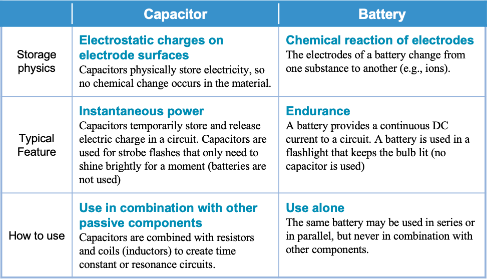
Both capacitors and batteries have the ability to store electricity and are called "energy storage devices. However, there are some basic differences between them as shown below.
Please refer to this article for a detailed explanation of capacitors.

Editorial supervision/Kazuyuki Iida
General Advisor, AIC tech Inc.
Born in the Tokyo area in 1956
M.S. of Sc, Sophia University, Tokyo, Japan. 1982
Over 35 years experience with knowledge on capacitor technology, i.e. R&D for high-performance capacitor and its materials, marketing activities at Hitachi Chemical Co, Ltd. and Hitachi AIC Inc. and Contributed articles on capacitors to public relations magazines, trade journals, and various handbooks.
Instructor of capacitor technology at the Technical Training Institute of Hitachi, Ltd. from 2005 to 2015.
General advisor to AIC tech Inc. from 2020.
- "Tantalum Electrolytic Capacitor"
The Electrochemical Society of Japan (ed.) Maruzen Handbook of Electrochemistry, 5th Edition, Chapter 15, Capacitors, Section 15.2.4 b (1998) - "Development Trend and Material Technology of Tantalum-Niobium Capacitors"
Technical Information Association of Japan Seminar June 2008 - Lead-Free Surface Mount Film Capacitors MMX-EC, MML-EC Series
Hitachi Chemical Technical ReportNo. 48. Product Introduction 2007 - "Film Capacitors for Electronic Devices"
Maruzen Capacitor Handbook, 5th Edition, Chapter 5, Film Capacitors, Section 5.2 (2009). - "Film capacitor MLC series for new energy"
Shinkobe Electric Co., Ltd. Shinkobe Technical Report Np. 22 (2012).
PDF Download