Capacitor Impedance Explained:
Guide on ESR, ESL, and Reactance
Introduction
Impedance is one of the most fundamental and important concepts for understanding the behavior of AC circuits. As electronic devices continue to operate at higher speeds and frequencies, a clear understanding of impedance has become increasingly important for circuit design, component selection, and ensuring reliability.
In this article, we explain the definition and physical meaning of impedance, starting with basic circuit elements such as resistors, capacitors, and inductors.
Contents
IMPEDANCE
- What is Impedancer
- ESR and ESL as important components of Impedance
- Equivalent Series Resistance : ESR
- ESR varies with frequency, why?
- Frequency-dependent and frequency-independent ESR
- ESR varies with temperature
- Equivalent Series Inductance : ESL
- ESR and ESL of Aluminum Electrolytic Capacitors
- Impedance Summary
What is Impedance
Impedance is the resistance to alternating current, measured in ohms. The magnitude of impedance is determined by resistance, capacitance, inductance, and frequency of alternating current. The term "impedance" is derived from the English word "impede," from the Latin "impedire." The name is derived from the fact that resistance, inductance, and capacitance impede the flow of current and voltage in an electric circuit where alternating current flows.
Resistance impedes the flow of current, both DC and AC. Capacitance stores charge and block DC , but allows AC to flow through it. Inductance generates a magnetic field that hinders current changes, but it is difficult for high-frequency alternating current to pass through. Impedance is also used as a parameter to describe the AC characteristics of electronic circuits and materials as well as electronic components*01.
*01 The human body also has impedance. By passing a weak electric current through the body and measuring impedance, the amount of water, body fat, and muscle mass in the body can be indirectly determined. https://www.jstage.jst.go.jp/art icle/jsmbe1963/33/3/33_3_18 4/_article/-char/ja/
Impedance definition
Impedance is expressed as the ratio of AC voltage to current at a given frequency and is defined as a complex number consisting of a real part and an imaginary part as in equation (01) *02.
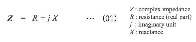
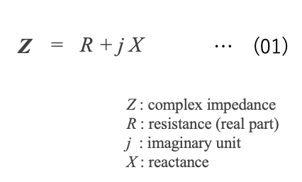
*02 Mathematically, impedance is treated as a vector quantity on the complex number plane.
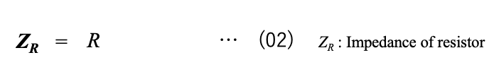
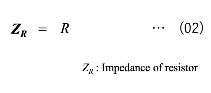
[Resistor] A resistor works the same way in both DC and AC circuits, dissipating power as Joule heat. Resistance is always positive, and resistance is directly proportional to impedance (equation (02)).
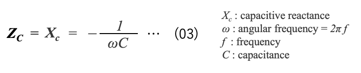
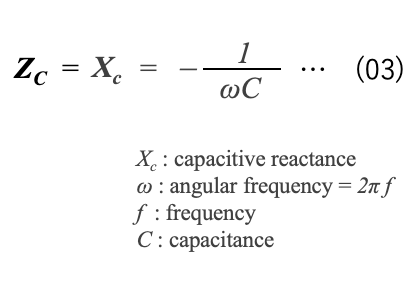
[Capacitor] A capacitor has an infinite resistance in a DC circuit, but in an AC circuit, it stores energy as an electric field and behaves like a resistance to the AC current (capacitive reactance *03 ). The impedance (Zc) of an ideal capacitor with no parasitic resistance is expressed as the capacitive reactance (Xc) in equation (03).
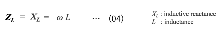
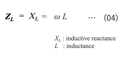
*03 When an alternating current flows through an inductor or a capacitor, a voltage is generated in these elements, causing them to behave like a resistance. This is called reactance.It is called "inductive reactance" for inductors and "capacitive reactance" for capacitors.
[Inductor] An inductor is considered to have zero resistance in a DC circuit, but in an AC circuit it stores energy as a magnetic field and behaves like a resistance to AC current (dielectric reactance). The impedance (ZL) of an ideal inductor with no parasitic resistance is only the inductive reactance (XL), thus equation (04)
Frequency dependence
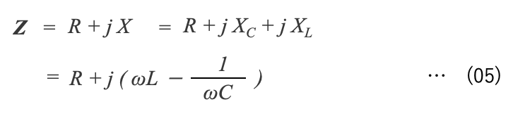
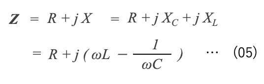
Considering an equivalent circuit (3-element model) consisting of capacitance, resistance, and inductance (Figure 1), the impedance Z of this equivalent circuit can be expressed by equation (05), which combines equations (01), (02), (03), and (04).

3-element model
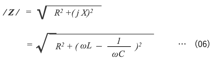
The absolute value of impedance, /Z/, can be expressed by equation (06) as the square root of equation (05).
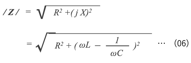
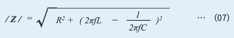
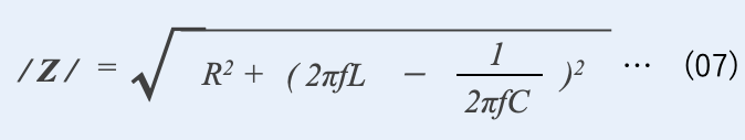
Replacing the angular frequency ω in equation (06) by the frequency f, impedance becomes a function of frequency expressed in equation (07). The frequency dependence of impedance can be illustrated using equation (07) as shown in Figure 2.

Schematic diagram of impedance versus frequency
The capacitive reactance (Xc: 1/2πfC) in equation (07) becomes smaller at higher frequencies and is eventually succeeded by the inductive reactance (XL: 2πfL). The frequency at which Xc and XL become equal is called the resonance frequency fr. The impedance at the resonant frequency is the resistance R *04 . The magnitude of the resistance R greatly affects the frequency response of the impedance.
*04 In a decimal circuit, capacitors with different capacitances are connected in parallel to provide a wide range of low impedance from low to high frequencies, and instantaneously supply energy to the semiconductor. (See Section 2.3.2 Equivalent Series Inductance (ESL))
Impedance of real capacitors
Figure 3 shows examples of frequency characteristics of impedance for aluminum electrolytic capacitors, leaded linear film capacitors, and chip-type multilayer ceramic capacitors. The graph shows a V-shape or U-shape, but the impedance minima and their frequency ranges vary depending on the type of capacitor and its capacitance.

Impedance versus frequency of various capacitors
The resistance of film and ceramic capacitors is smaller than the impedance due to capacitive or inductive reactance, so the impedance curve shows a sharp V-shape. Aluminum electrolytic capacitors have larger capacitance and higher resistance than film and ceramic capacitors, resulting in a smooth U-shaped curve*05 .
In an actual capacitor, resistance due to electrodes and electrolyte and inductance such as lead wires are parasitic in series with the capacitance. These are called "equivalent series resistance (ESR)" and "equivalent series inductance (ESL)", respectively*06 . In addition to the true capacitance due to the dielectric, double layer capacitance and distributed capacitance between the electrolyte and electrode also exist as parasitic components, which are also components of impedance.
*05 By combining the different impedance characteristics of various capacitors, a noise filter with a wide frequency bandwidth can be constructed.
*06 "ESR" and "ESL" are preferred to be as small as possible because they cause a (common mode noise to be generated when switching current flows. Details of "ESR" and "ESL" are explained in section 2.3.
- Impedance is the resistance to alternating current.
- The impedance of a capacitor consists of resistance, capacitive reactance and inductive reactance.
- The frequency response of the impedance varies from capacitor to capacitor.
TIPS
The impedance of an ideal capacitor is only the imaginary component (1/ωC) of the capacitive reactance (XC) (equation 03), but since an actual capacitor has resistance, the resistance (R) is the real component of the impedance*07. Let δ be the angle when impedance is expressed in terms of resistance R and 1/ωC (Figure 4), tanδ is expressed by equation (08).

Vector expression of R and Xc
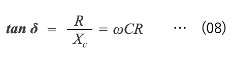
From equation (08), we can see that tan δ is the ratio of resistance to capacitive reactance. When an AC voltage is applied to the capacitor, the AC current should advance 90°, but due to the equivalent series resistance component, it advances only 90°-δ. The smaller tan δ is, the better.
*07 The major components of this resistance are the dielectric and the electrodes. When the dielectric cannot follow the direction changes in AC voltage, dielectric losses are generated. This is sometimes referred to as tanδ.
ESR and ESL as important components of Impedance
Figure 5 shows the frequency characteristics of impedance and ESR of our aluminum electrolytic capacitor (VGR type rated at 4700 μF 400V) As explained in Section 2.1 (3), impedance decreases with frequency at low frequencies (around several kHz) due to capacitive reactance. At frequencies above several tens of kHz, the impedance increases due to inductive reactance caused by ESL. Actual capacitors have parasitic ESR and ESL, which are important components of impedance. This section provides definitions and characteristics of ESR and ESL.

Impedance, ESR versus frequency
Equivalent Series Resistance : ESR
Almost all capacitors have an ESR of a few milliohms to several ohms; as discussed in Section 2.1 (3), ESR is a parasitic resistance in series with capacitance that causes the energy stored in the capacitor to be dissipated as Joule heat. In other words, the higher the ESR of a capacitor, the more power is consumed as heat. For example, in a circuit with a large current flow, such as a power smoothing circuit, the amount of power consumed by the ESR becomes large, causing the capacitor to self-heat and raise its temperature. A significant temperature rise can fatally damage or even break the capacitor. In addition, temperature rise causes aging degradation, which shortens the expected life of the capacitor even if actual damage or destruction does not occur. Thus, ESR of capacitors is an important characteristic along with capacitance and withstand voltage.
ESR varies with frequency, why?
As shown in Figure 5, ESR varies with frequency. However, resistance should have no frequency dependence, since resistance works the same way for both DC and AC. This discrepancy can be explained by the equivalent circuit (4-element model, Figure 6), which assumes that "a capacitor has not only a resistance parasitic in series with the capacitance but also a resistance parasitic in parallel due to dielectric loss.

Equivalent circuit, 4-element model *08
*08 In the equivalent circuit of a capacitor, the parasitic capacitance of the capacitor may be considered in addition to the capacitor's equivalent capacitance C.Parasitic capacitance is the capacitance that occurs between the electrodes of a capacitor and between the electrodes and the surrounding conductors. This parasitic capacitance is expressed as a series capacitance and plays an important role at high frequencies. However, since parasitic capacitance is the smallest capacitance in the equivalent circuit of a capacitor, it is ignored in this section.
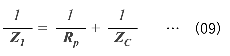
(1) Impedance Z1
In the equivalent circuit shown in Figure 6, the impedance Z1 of the part where the dielectric loss is parasitic in parallel to the capacitance (Figure 6a) can be expressed by Equation (09) using the impedance ZC of the capacitance and the resistance Rp due to dielectric loss.

Impedance Z1 of the part where dielectric loss is parasitic in parallel to the capacitance

Impedance Z1 of the part where dielectric loss is parasitic in parallel to the capacitance
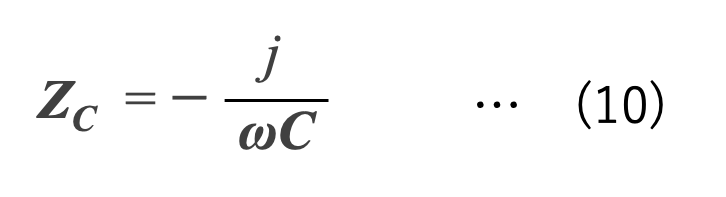
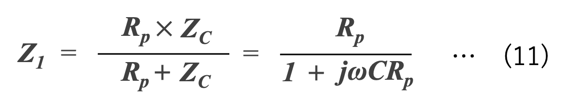
Since the impedance of capacitance ZC can be expressed as capacitive reactance in Equation (10), Z1 can be expressed as equation (11) from equations (09) and (10).
(2) Impedance Z2
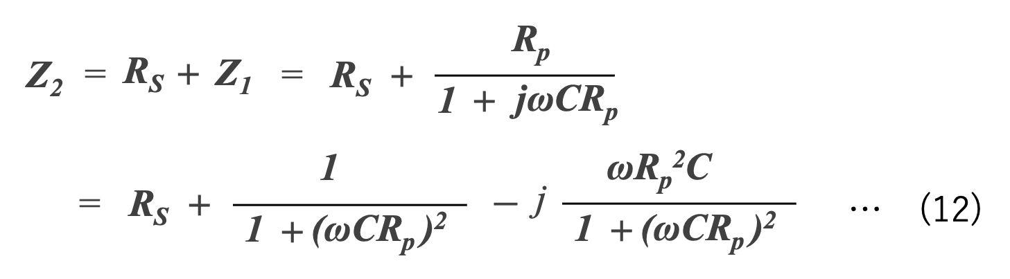
The impedance Z2 when a series resistance Rs is parasitic on Z1 becomes equation (12) by adding Rs to Z1 as shown in Figure 6b.

Impedance Z2 , sum of Rs and Z1

Impedance Z2 , sum of Rs and Z1
(3) Impedance Z of 4-element model
The impedance Z of the 4-element model (Figure 6c) with inductance L parasitic in series with Z2 is given by equation (13).

Equivalent circuit of 4-element model and impedance
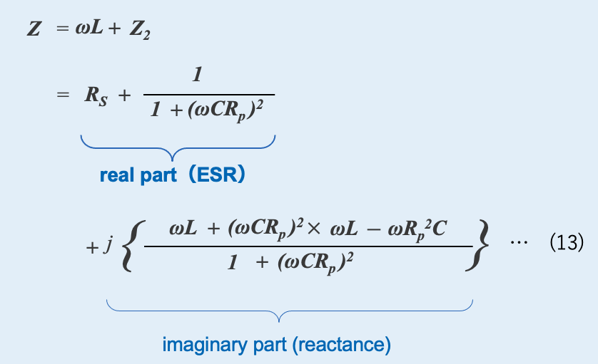
The real part of equation (13) is the ESR, and the second term of the real part includes the angular frequency ω . Therefore, the ESR can be considered to have a frequency characteristic.
Frequency-dependent and frequency-independent ESR
From Equation (13), we can see that ESR is composed of "frequency-independent resistance (RS)" and "frequency-dependent resistance (Rf)". Then, what are those resistors?
(1) What is a frequency-independent resistance (RS)?
The metal terminals, electrodes, and internal wiring of a capacitor fall into this category. They behave as resistors to both DC and AC, and their energy loss does not vary much with temperature or frequency. However, at high frequencies, the skin effect of the electrodes increases, and at high currents, the resistance loss of the terminals and internal wiring cannot be ignored.
(2) What is frequency-dependent resistance (Rf)?
There are two types of resistance to this. One is the resistance (Rd) related to dielectric loss, which is related to dielectric polarization and relaxation. In ceramic and film capacitors, the dielectric loss of the dielectric is the main cause of the overall ESR. The other is the resistance (Ro) when the capacitor forms a distributed constant circuit with a complex combination of capacitance and resistance.
The electrodes of aluminum electrolytic capacitors and tantalum capacitors are porous materials with a large surface area*09 and are filled with electrolyte or conductive polymers. As a result, these capacitors form a complex distributed constant circuit with parallel capacitances and series resistances, as shown in Figure 7. At low frequencies, all capacitances function, but at higher frequencies, the capacitances in the deeper holes (where the resistance is higher) apparently disappear and the resistance becomes smaller.
*09 Please refer to Essential Characteristics of Capacitors (CAPACITANCE), Section1.5(1) in details.

Schematic diagram of fine structure and equivalent circuit of aluminum electrolytic capacitor
Although it is difficult to explain the frequency dependence of ESR in detail, it is said that the dielectric loss component Rd is dominant at low frequencies from 1kHz to 10kHz, the resistance component Ro due to the distributed circuit is dominant in the intermediate frequency range from tens to hundreds of kHz, and RS is dominant at high frequencies above 1MHz, as shown in Figure 8 *10 .

Schematic diagram of ESR of each components versus frequency
Figure 9 compares the ESR frequency response of various capacitors. The film capacitor shows extremely small ESR characteristics due to its small Rd and RS and almost no R0 . Ceramic capacitors have large Rd but small R0 and RS. Aluminum electrolytic capacitors and tantalum capacitors have a high ESR due to the large size of all three elements.

ESR versus frequency of various 10μF capacitors
ESR varies with temperature
The ESR of a capacitor varies not only with frequency but also with temperature: if the main factor of ESR is metal, the ESR shows a positive temperature characteristic*11, and if it is a semiconductor, a negative temperature characteristic*12. The ESR of aluminum electrolytic capacitors using the electrolyte is lower at higher temperatures and is higher at lower temperatures, but the change is larger than that of other capacitors. This detail is explained in section 2.3.
The ESR values in capacitor manufacturer's data sheets are those at a temperature of 20 to 25°C and a frequency of 120 Hz or 100 kHz. However, some capacitor manufacturers or varieties may specify ESR at lower temperatures or at various frequencies. Therefore, it is necessary to contact the manufacturer to select a capacitor with the appropriate ESR for the operating temperature and frequency of the application.
*11 The electrodes of ceramic and film capacitors are made of copper, precious metals, or aluminum. The ESR of these capacitors exhibits a positive temperature characteristic that is low at low temperatures and high at high temperatures.
*12 Manganese dioxide used as cathode of tantalum capacitors has semiconducting property. Therefore, tantalum capacitors exhibit a negative temperature characteristic with a low ESR at high temperatures.
Equivalent Series Inductance : ESL
At high frequencies, pay attention to ESL
Inductance acts like resistance to AC current. Each of the electrodes, external / internal leads and terminals of a capacitor has some inductance. The sum of such inductances connected in series is called equivalent series inductance (ESL). The effect of ESL is observed only at high frequencies, and above the resonant frequency fr, the capacitor behaves like an inductor*13. Since the fr is the frequency when the capacitive reactance (Xc) and inductive reactance (XL) are equal, solving equation (15), where the imaginary part of equation (05) becomes zero, yields equation (16), which represents the resonant frequency fr .
*13 Resonant frequency is an important factor in RF circuits.
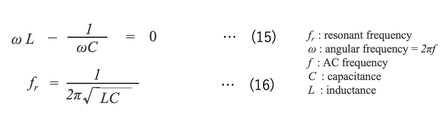
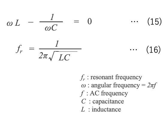
Equation (15) shows that the smaller the inductance, the higher the resonant frequency, even if the capacitance is the same. As shown in Figure 10, a lower-inductance capacitor has a smaller impedance at higher frequencies and can be used in circuits with higher switching frequencies.

Impedance versus frequency of capacitors with different ESL values*14
Low ESL type capacitors
Large inductance causes induced voltage spikes that can damage semiconductors. Furthermore, the interaction between stray inductance and capacitance can generate noise, degrading circuit stability and power quality.
Digital circuits driven at high frequencies are increasingly using low ESL, especially ceramic capacitors. High-speed memory chips and microprocessors use many decoupling capacitors (Figures 11 and 12). This is to transfer the energy stored in the capacitors instantaneously. The speed at which energy is transferred depends largely on the ESL of the capacitor; the higher the ESL, the slower the speed. Today's digital circuits require high switching speeds and low ESL capacitors. As switching speeds increase, the demand for capacitors with low inductance will continue to increase.

Schematic diagram of decoupling capacitor configuration for microprocessor*15,*16
*15 Aluminum electrolytic or tantalum capacitors are often used together with ceramic capacitors.

Block circuit diagram of CPU、Decoupling capacitor、VRM*17,*18,*19
*17 Decoupling Capacitor - an overview | ScienceDirect Topics
*19 Low ESR and low ESL are essential factors for decoupling capacitors.
In power electronics technology field, as the application of next-generation power semiconductors*20 such as silicon carbide (SiC) and gallium nitride (GaN) expands, capacitors with low ESL are also required. This is due to the need to suppress self-heating while enhancing the protection of power semiconductors, especially in DC links for high-frequency switching and industrial inverters. Furthermore, capacitors with low ESL reduce peak voltage spikes, allowing the use of lower rated power semiconductors. Noise is also reduced, which improves the output quality of switching power supplies.
ESL is primarily due to the internal construction and connections of the capacitor element, and these improvements can reduce ESL. To lower the inductance, it is necessary to make the conductor wider and shorter in length, and to improve the structure of the lead wires and external terminals and the method of connection with the capacitor element. Capacitor manufacturers are making progress in technological development for lower ESL.
*20 While silicon, Si, is a single substance, SiC is a compound of carbon and silicon, and GaN is a compound of gallium and nitrogen, and these are called compound semiconductors. SiC and GaN have high breakdown field strength and can achieve the same breakdown voltage as silicon with a thiner insulation layer.
- ESR is a parasitic resistance in series with capacitance that causes the energy stored in the capacitor to be dissipated as Joule heat.
- While a lower ESR may be better, it should be noted that ESR varies with frequency and temperature.
- Since ESL can cause spike voltages and noise at high frequencies, a type of capacitor with reduced ESL should be used if necessary.
ESR and ESL of Aluminum Electrolytic Capacitors
As shown in Section 2.2.1, Figure 7, aluminum electrolytic capacitors using electrolytic solution are characterized by a larger ESR than other capacitors. In addition, cylindrical aluminum electrolytic capacitors have external leads and leads (lead tabs) inside the capacitor, resulting in a larger impedance at high frequencies.
For this reason, in recent, there are products that apply conductive polymers to lower ESR and chip-type products that achieve low ESR and low ESL by stacking multiple elements on a flat plate.
ESR Features of electrolyte-type aluminum capacitors
Aluminum electrolytic capacitors with low ESR are also required in power electronic circuits, because using capacitors with low ESR suppresses power loss and internal heat generation, and thus longer life can be expected.
Aluminum electrolytic capacitors with electrolytic solution are often used in power electronics circuits. These capacitors consist of an anode, cathode, separator, electrolyte, and lead tabs (Figure 13). Of these, the separator and electrolyte have a significant effect on ESR.
The separator prevents direct contact between the anode and cathode foils and at the same time maintains the function of the electrolyte by holding the electrolyte. For this reason, a low-density separator that can easily store electrolyte is suitable for low ESR*21.

The structure and materials of aluminum electrolytic capacitor element

The structure and materials of aluminum electrolytic capacitor element
The viscosity and conductivity of the electrolyte also have a significant effect on ESR*22. The lower the viscosity of the electrolyte, the easier it is to penetrate the anode and separator, and the higher the conductivity, the smaller the ESR. However, low viscosity and high conductivity electrolytes risk compromising withstand voltage and service life, so capacitor manufacturers address this tradeoff with various technologies.
The viscosity and conductivity of electrolyte are highly dependent on temperature, with higher viscosity and lower conductivity at lower temperatures resulting in a larger ESR of the capacitor (Figure 14). Depending on the type of solvent and the ionic radius of the solute, the conductivity of electrolyte at temperatures below -20°C decreases significantly to 1/10 to 1/100 of room temperature.
*21 The separator is made of a special paper with low impurities and high water absorbency. The thickness of the separator is approximately 30 to 75 μm, and it is used according to the rated voltage of the capacitor. For high-voltage capacitors, several layers of paper or high-density paper may be used. Kraft paper made of wood fiber and manila paper made of vegetable fiber are used for separators.
*22 The conductivity of an electrolyte is highly dependent on its concentration and viscosity. Electrolytes with high solubility and high ionization will have a high charge density. Solvents with small viscosity η [Pa・s] and electrolytes with small ionic radius have larger mobility μ [m2/V・s].

ESR versus frequency at various temperature
(AICtech Type VGR 400V 4700μF)
Low ESL aluminum capacitor
The ESL of an aluminum electrolytic capacitor element is usually less than 2 nH, but when ESL is measured between external terminals, it is 10 to 30 nH for radial leaded aluminum electrolytic capacitors, 20 to 50 nH for screw terminal type, and about 200 nH for axial leaded type (Figure 2-15). Therefore, aluminum electrolytic capacitors have a large impedance at high frequencies.
In DC link applications such as high-frequency switching and industrial inverters, low ESL capacitors are required to reduce self-heating while providing enhanced protection for power devices. Since capacitor ESL, along with other connections and cables, can cause voltage spikes, snubbers must be placed in each phase of the inverter. Lowering the ESL of the capacitor can reduce the overall inductance and possibly eliminate the need for snubber circuits in each phase of the inverter.

Typical ESL of aluminum capacitor by type
To reduce ESL, it is effective to optimize the internal structure so that all magnetic fields generated by the current flowing through the capacitor are cancelled out. Specifically, this can be achieved by shortening the distance between the winding element and the terminals, as well as between the internal lead tabs of the winding element and the external terminals.
Impedance Summary
A capacitor is not an ideal capacitive element having only capacitance; it has parasitic resistance and inductance. Therefore, capacitors have an impedance
- Impedance is the resistance of an AC circuit and is measured in ohms (Ω).
- The impedance of a capacitor consists of capacitive reactance, equivalent series resistance (ESR), and inductive reactance (ESL).
- The smaller the ESR, the more desirable the characteristic, since the energy stored in the capacitor is dissipated as heat. Note, however, that it varies with frequency and temperature.
- ESL is mainly caused by the internal structure of the capacitor element and its connections, which can cause spike voltages and noise at high frequencies.
- Aluminum electrolytic capacitors have a larger ESR than other capacitors, and ESL is caused by lead wires and other factors.
- Low ESR and low ESL capacitors have been developed to meet market requirements.
TIPS
Capacitors with reduced ESL are now used in digital circuits, especially in capacitors for decoupling. In power electronics, power semiconductors with fast switching in the high power range are now used in DC links, requiring lower inductance in circuits and peripheral components. This is due to the many performance and cost advantages offered by lower ESL. In the future, film capacitors and aluminum electrolytic capacitors will continue to be made with lower ESL*23 .
*23 What are the main reasons why low ESL is required for capacitors?The ability to use higher DC link voltages reduces voltage peaks during switch-off and short-circuit conditions. Power semiconductors that can be driven at lower voltages can be used, thus reducing the cost of power semiconductors.High-speed switching becomes possible and switching losses are reduced.The number of capacitors connected in parallel can be reduced without increasing the inductance of the capacitor bank (ripple current characteristics of capacitors are improved).The number of capacitors used can be reduced, which in turn reduces assembly man-hours, space requirements, and weight, enabling smaller systems and lower costs.This is because of such advantages as the following.
Please refer to this article for a detailed explanation of capacitors.

Editorial supervision/Kazuyuki Iida
General Advisor, AIC tech Inc.
Born in the Tokyo area in 1956
M.S. of Sc, Sophia University, Tokyo, Japan. 1982
Over 35 years experience with knowledge on capacitor technology, i.e. R&D for high-performance capacitor and its materials, marketing activities at Hitachi Chemical Co, Ltd. and Hitachi AIC Inc. and Contributed articles on capacitors to public relations magazines, trade journals, and various handbooks.
Instructor of capacitor technology at the Technical Training Institute of Hitachi, Ltd. from 2005 to 2015.
General advisor to AIC tech Inc. from 2020.
- "Tantalum Electrolytic Capacitor"
The Electrochemical Society of Japan (ed.) Maruzen Handbook of Electrochemistry, 5th Edition, Chapter 15, Capacitors, Section 15.2.4 b (1998) - "Development Trend and Material Technology of Tantalum-Niobium Capacitors"
Technical Information Association of Japan Seminar June 2008 - Lead-Free Surface Mount Film Capacitors MMX-EC, MML-EC Series
Hitachi Chemical Technical ReportNo. 48. Product Introduction 2007 - "Film Capacitors for Electronic Devices"
Maruzen Capacitor Handbook, 5th Edition, Chapter 5, Film Capacitors, Section 5.2 (2009). - "Film capacitor MLC series for new energy"
Shinkobe Electric Co., Ltd. Shinkobe Technical Report Np. 22 (2012).
PDF Download