Capacitor Failures
(The 15 practical case studies in various capacitor applications)
Introduction
AIC tech capacitors are designed and manufactured under strict quality control and safety standards. To ensure safer use of our capacitors, we ask our customers to observe usage precautions and to adopt appropriate design and protection measures (e.g., installation of protection circuits).
However, it is difficult to reduce capacitor failures to zero with the current level of technology. Therefore, this report explains troubleshooting (diagnosis of failures and appropriate measures) to ensure proper and safe use of capacitors.
Contents
- Perhaps a capacitor has failed?
- How does a capacitor fail?
- The 15 Practical Case Studies
- Aluminum Electrolytic Capacitors
Case 1 A Capacitor Started Smoking
Case 2 A Capacitor Generated Heat and Failed
Case 3 Capacitance Decrease
Case 4 Vapor Erupted From A Capacitor
Case 5 A Capacitor Failed at Hot Place
Case 6 An Overcoated Capacitor Failed
Case 7 A Capacitor Do Not Like Cold
Case 8 Capacitor's Best-Before Date?
Case 9 Spark from Al Electrolytic Capacitor
Case10 Horizontally Mounted Al Electrolytic Capacitor
Case11 A Capacitor in Series Strings Has Failed - Film capacitors
Case12 DC Film / AC Film Capacitor
Case13 What's The Electrode, Metalized or Foil?
Case14 A Capacitor Suffered From Thermal Stress
Case15 Strange Sound Came From A Film Capacitor
- Aluminum Electrolytic Capacitors
- Appendix (What's A Capacitor)
- Conclusion
Perhaps A Capacitor Has Failed?
When a capacitor fails, it loses its basic functions of storing charge in DC and removing noise and ripple current. In the worst case, the capacitor may ignite, resulting in a fire hazard.
If any of the following abnormalities are observed in the capacitor, immediately shut off the power supply and take appropriate measures.
- Swollen and deformed case
- Cracks in the case
- Gap between case and sealing area
- Open pressure-relief vent
- Rupture of case, damage to sealing area
- Hot, generating heat
- Smoking
- Liquid leakage
- Strange noise
- Strange odor
Even if the appearance of the failed capacitor is not abnormal, care must be taken when handling the capacitor. In particular, take care to avoid electric shock*1 due to residual charge on the capacitor, contact of electrolytic solution*2 with the skin or eyes, and inhalation of electrolytic solution vapors.
*1 When the terminal of a charged capacitor is shorted (shortcircuited) to make the voltage between the terminals zero, and then the short-circuit is released, a voltage called a "recovery voltage" is generated again at the terminal of the capacitor. The recovery voltage is clearly observed after DC voltage has been applied for a long time, especially when the temperature rises.
*2 The electrolyte in aluminum electrolytic capacitors contains no hazardous substances. AICtech also provides product information sheet. However, the electrolyte gassed by combustion has a pungent odor.
How does a capacitor Fail?
Capacitors have three main failure modes
(1) Open failure, in which the resistance (impedance) of the capacitor reaches an extreme value
(2) Short-circuit failure, in which the insulation is degraded and a DC current passes through
(3) Failure in which capacitor characteristics such as capacitance and loss change significantly beyond specifications
Which failure is more likely to occur depends on the type of capacitor. The U.S. IITRI document*3 summarizes the relative occurrence of failure modes for each capacitor as shown in Table 1. Mica and tantalum capacitors are more likely to fail in the early period of use (early failure), while aluminum electrolytic capacitors are more likely to experience wear-out failure due to aging use. In the case of film capacitors, when a local short circuit failure occurs, the shorted area may temporarily self-heal.

*3 IIT Research Institute, Failure Mode, Effects and Criticality Analysis (FMECA) , 1993
IIT : Illinois Institute of Technology
Open mode failure
An open mode failure in a capacitor can have undesirable effects on electronic equipment and components on the circuit. For example, if a large capacitor is used in the smoothing circuit of a power supply, a large wave-like voltage*4 can be converted to a flat DC voltage, but if the capacitor is open, a large voltage wave is directly applied to the circuit, which may cause semiconductors and other components to fail.
*4 It's called ripple voltage.
Causes of open failures
For example, when a capacitor was mounted on a board, strong stress on the capacitor damaged the external terminals, resulting in an open (the area shown in red in Figure 1).
An open failure also occurred if the internal wiring between the capacitor element and the external terminal is broken or significantly increased resistance at connections (the dashed red line in Figure 2).

Lead wire disconnection

Internal leads disconnection
There are various/many specifications and connection methods of external terminals and internal wiring. And it depends on the type of capacitor, but factors that can cause open failures include vibration and shock during mounting on the board and transportation, as well as placement of the device on the board.
Short-circuit mode failure
When a capacitor fails a short circuit (Figure 3), DC current flows through the capacitor and the shorted capacitor behaves like a resistor. For example, if a capacitor, placed between the input line and ground to remove AC current such as ripple current or noise, is shorted, DC current directly flows from the input to ground.
Since a real capacitor has a resistance*5, when current flows through the shorted capacitor, Joule heat is generated and makes the capacitor heat up. Since the magnitude of Joule heat is proportional to the resistance (R) and the square of the current (I2), the heat generated in a circuit with a large current flow can be so large that the capacitor may emit smoke.
Rapid heat generation can also destroy the case or encapsulation and cause the materials inside the capacitor to react with oxygen in the air, resulting in a risk of ignition.

Current flow diagram

Current flow diagram
*5 It is called Equivalent Series Resistance (ESR) which consists of electrodes and lead wires.
Causes of short-circuit failures
Also, since the thickness of dielectric is extremely thin*6, excessive mechanical stress on the capacitor can damage the dielectric and cause a short circuit failure. In addition to taking electrical and environmental factors into consideration, it is also important to devise ways to prevent shock and vibration from being applied to the capacitor.
*6 The thickness of the dielectric film of film capacitors is usually less than 5 µm, which is about 1/2 to 1/3 the thickness of a household product packaging film.
The dielectric thickness of aluminum electrolytic capacitors is only a few hundred nm at the thickest.
Changes of Electrical Characteristics
The most basic characteristic of a capacitor is capacitance (C), but it has many other characteristics such as equivalent series resistance (ESR), dielectric loss tangent (tanδ), insulation resistance, leakage current, withstand voltage, equivalent series inductance (ESL) and impedance. Each characteristic has a standard value specified by JIS, IEC, or other norms.
However, aging, use in excess of ratings, use in harsh environments, and mechanical stresses can change these characteristics and degrade the functionality of electronic equipment.
Electrolyte Leakage
Aluminum electrolytic capacitors and electric double-layer capacitors (EDLC) *7 use a conductive liquid called electrolyte. If this electrolyte leaks out of the capacitor housing or sealing area, it can cause the capacitor to lose its function, short circuit the circuit board, or have a negative effect on surrounding components.
The main causes of electrolyte leakage are short circuits and damage to the sealing parts due to aging. Specific examples are presented in Chapter 3.
*7 EDLCs are capacitors that utilize the double layer capacitance stored in the electric double layer formed at the interface between the activated carbon electrode and the electrolyte.
15 Practical Case Studies
When a capacitor fails, a variety of electrical, chemical, and physical anomalies are seen. For this reason, customers use a variety of terms to describe failures (Figure 4).

A variety of terms, customers describe capacitor failures
In order to prevent capacitor failure and to use capacitors safely, it is very important to understand the causes and processes of capacitor failure and to take appropriate countermeasures.
Failure of capacitors is caused by a combination of various factors. The causes and processes of failure differ depending on the type of capacitor.
In this section, failure examples, causes and countermeasures for aluminum electrolytic capacitors and film capacitors are explained.
Aluminum Electrolytic Capacitors *8
Aluminum electrolytic capacitors are one of the most essential electronic components in power and electronic circuits because of their small size and high capacitance compared to other capacitors.

Aluminum electrolytic capacitors
Aluminum electrolytic capacitors are also known as chemical capacitors because they use chemical reactions. Therefore, the performance of aluminum electrolytic capacitors is greatly affected by environmental and electrochemical factors such as temperature and atmosphere, and rapid chemical reactions can cause failure.
*8 Aluminum electrolytic capacitors are available in wet type using electrolyte, solid type using conductive polymers, etc., and hybrid type using a combination of both.
In this section, we focus on wet type aluminum electrolytic capacitors using electrolyte.
The basis of this capacitor are discussed in Chapter 4.
Case 1 Capacitor Started Smoking
(A capacitor failed and the vent ruptured)
The pressure-relief vent*9 of an aluminum electrolytic capacitor used for smoothing the power circuit was ruptured and a capacitor started smoking.

Outlook of snap-in aluminum electrolytic capacitor
and pressure-relief vent
*S-shape and diagonal line

The ruptured pressure-relief vent
When the internal pressure of the capacitor rises, the pressure valve opens and electrolyte (gas) is released.
*9 Wet type aluminum electrolytic capacitors are usually equipped with pressure-relief vent structures that limit the maximum internal pressure. These vents are intended to rupture and release the gas pressure (Figure 7).
What is the cause of the failure?
Due to input voltage fluctuation, an overvoltage exceeding the rated voltage was applied to the aluminum electrolytic capacitor. As a result, the capacitor failed short and DC current flowed into the capacitor. Then gas was generated from the electrolyte, and it boosted the inner pressure of the capacitor. Finally, the pressure-relief vent ruptured and the electrolyte blew out as aerosol like smoke.

Input Voltage Fluctuation
How to do, what to do?
Before selecting a capacitor, please check the followings in advance.
- Is there the voltage fluctuating?
- The peak value (Vtop) of the fluctuating voltage does not exceed the rated voltage.
- The negative peak value (Vbottom) of the fluctuating voltage is not in excess of zero and is not the reverse voltage.
- The fluctuation amplitude (ΔV*10) may be large, etc.
*10 ΔV is the difference between Vtop and Vbottom, also expressed as Vpp.
Please also note;
If the capacitor heats up abnormally, it may short-circuit and eventually catch fire. Fire may also spread if the electrolyte*11 spurts out and splashes onto surrounding flammable materials.
*11 The electrolyte is an ion-conductive liquid that acts as an effective cathode.
Case 2 A Capacitor Generated Heat and Failed
(High ripple current flowed into a capacitor)
An aluminum electrolytic capacitor, used in the DC link of an inverter circuit, shorted and generated heat. Finally, the pressure-relief vent ruptured.
What is the cause of the failure?
High ripple current flowed into the capacitor and the capacitor heated up beyond its design value. The heat generated reduced the insulation of the capacitor. As the result, the capacitor failed short-circuit and the gas generated from the electrolyte. Finally, the pressure-relief vent ruptured and the electrolyte blew out as aerosol like smoke (Figure 9).
How to do, what to do?
Please check if the magnitude and waveform of the ripple current expected at the design stage meet the capacitor specifications.
Select a capacitor by considering the ripple current allowed by the multipliers for capacitance, temperature, and frequency.

The electrolyte blew out as aerosol like smoke
Please also note;
The allowable ripple current is determined by the ambient temperature, equivalent series resistance (ESR) at the frequency of the AC signal, thermal resistance determined mainly by the surface area of the capacitor (heat dissipation area), and applied cooling. Temperature rise due to ripple current has a significant affect on capacitor failure. Please contact us for capacitor selection.
Case 3 Capacitance Decrease
(Frequent charging and discharging cycle application)
The capacitance of an aluminum electrolytic capacitor used in a circuit, where frequent charging and discharging cycle applied, decreased in a relatively short period.
What is the cause of the failure?
An aluminum electrolytic capacitor consists of an anode foil, whose surface is oxidized to form a dielectric, an aluminum cathode foil, and a separator (Figure 10). The capacitance of the anode foil section, C1, and the cathode foil section, C2, are connected in series (Figure 11), so the equivalent capacitance C is expressed by Equation 1.

Structure of wet-type aluminum electrolytic capacitor

Diagram of Equivalent series capacitance "C" and equation
When an aluminum electrolytic capacitor is frequently charged and discharged, the following chemical reactions occur continuously on the surface of the cathode foil.
[During charge]:
Electrolytic solution electrolyzes to produce gas.
[During discharge]:
The charge on the anode foil is moved to the cathode foil.
Then cathode foil is oxidized and its capacitance decrease.
As a result, open mode failure which the pressure-relief vent is open and/or the capacitance decrease. This failure mode may occur not only the charging/discharging cycles, but when large voltage fluctuations are applied to the capacitor.
How to do, what to do?
For circuits that frequently repeat charging and discharging, such as welding machines, servo motor drive and photoflashes, a special designed capacitors which are capable of enduring such conditions should be selected and used. Please contact us.
Please also note;
The capacitor whose capacitance has decreased should be replaced as soon as possible. The capacitor may be worn out, and continued use without replacement may result in an open failure or short circuit.
Case 4 Vapor Erupted From A Capacitor
(A heat sink disturbed pressure-relief vent operation)
Snap mount type aluminum electrolytic capacitors are used in power supply devices. The heat sink and the top of the capacitor were placed close together to reduce the thickness of the device.
When an overvoltage was intentionally applied to the capacitor in order to perform an abnormal condition test, the pressure-relief vent on the top of the capacitor did not open and the capacitor still continued to heat up. Subsequently, it was observed the electrolyte vapor erupted from the bottom of the capacitor (Figure 12).

The heat sink disturbed pressure relief vent operation.
Vapor erupted from capacitor bottom.
What is the cause of the failure?
An overvoltage was applied to the capacitor, resulting in a short-circuit fault and heat generation. The heat caused the electrolyte to vaporize and generate gas, which increased the pressure inside the capacitor.
However, the pressure-relief vent did not open, because the heat sink interfere with the operation of vent, so gas erupted from the sealing part at the bottom of the capacitor, causing the capacitor to short-circuit.
The wiring pattern on the board short-circuits, causing a spark was generated and smoke was emitted.
How to do, what to do?
The requirements for the pressure-relief vent to open and the design rules for safety have been reviewed and the necessary space has been secured (Figure 13). If sufficient space cannot be secured, we recommend the type with pressure-relief vent on the side of capacitor (Figure 14).

Actions
A space is provided between the heat sink and the capacitor where the pressure valve can operate, and an insulating sheet is installed on the heat sink.

The type with pressure-relief vent on the side of capacitor
Please also note;
Provide the necessary space for the pressure-relief vent of the capacitor to operate. When the vent opens, the electrolyte vapor will be blown out. Since the electrolyte is conductive, if it adheres to the wiring or circuit pattern, the circuit will be short-circuited. If the vent, which has been deformed by opening, contacts the enclosure of the equipment, the input voltage and the enclosure may be connected, resulting in a ground fault.
Case 5 A Capacitor Failed at Hot Place
(Temperature distribution on the board and capacitor)
Five aluminum electrolytic capacitors of the same rating and lot were connected in parallel and used, but one of these capacitors failed and the pressure-relief vent ruptured.
What is the cause of the failure?
The failed capacitor was mounted away from the other four capacitors. There were components that generate heat close to the capacitor (Figure 15). Due to the radiated heat from the heating components, this capacitor was exposed to higher temperatures than the other capacitors. This resulted in a wear-out failure and pressure-relief vent opened within a relatively short period of time.

Temperature distribution on the board and capacitor location during circuit work
How to do, what to do?
The capacitor mounting locations have been changed to reduce the effects of radiant heat from heat-generating components. The cooling method for the circuit board has also been changed, and long-life capacitors have been used to handle high ripple currents.
Please also note;
(1) The ripple current causes the capacitor to heat up and its temperature to rise. The larger the temperature rise, the shorter the life of the capacitor. When using multiple capacitors connected in parallel or series, please pay attention to the ESR of each capacitor, temperature distribution in the system's housing, radiation heat, and wiring resistance.*12
*12 Detailed analysis showed that the failed capacitor had a larger current load due to the length of the wiring than the other capacitors.
(2) When multiple capacitors are used, please calculate the life of the capacitor with the highest temperature as the standard. When calculating the life, make sure that the difference between the temperature (measured value) at the hottest spot of the capacitor and the ambient temperature (temperature rise value) is within the allowable range.
(3) Compared to other components, capacitors are relatively large and not heat-resistant. For this reason, thermal design to properly cool capacitors, such as the location and specifications of cooling fans, heat dissipation grilles, and air conductors, should be considered. Please consult with us if necessary.*13
*13 Our capacitors are designed to be cooled by a blow-off fan that directs the cooling air to the capacitor. Please consult us if you use an exhaust fan for air cooling.
Case 6 An Overcoated Capacitor Failed
(Do not cover the capacitor with coatings or resins)
To prevent vibration-induced failure of snap-in aluminum electrolytic capacitors mounted on boards, the capacitor body was covered with a coating material (Figure 16). However, the electrolyte leaked and the capacitors failed.

A overcoated capacitor on a substrate
What is the cause of the failure?
The electrolyte in aluminum electrolytic capacitors evaporates during operation, releasing gases into the atmosphere through the rubber seal (packing). The sealing disk and the capacitor body are equipped with a pressure-relief vent.
Therefore, if the capacitor is covered with resin or other material, gas dissipation and the operation of the pressure-relief vent will be prevented.
In this case, the coating material blocked the pressure-relief vent and prevented it from operating, resulting in damage to the capacitor seal, electrolyte leakage, and capacitor failure*14.
*14 The electrolyte is filled into the capacitor element, which consists of an anode foil, cathode foil and separator, and the element is immersed in the electrolyte.
How to do, what to do?
Do not cover the capacitor with coatings or resins.
Most of our aluminum electrolytic capacitors can withstand vibration tests in which vibration acceleration of up to 10G is applied. Please refer to the specifications of each product for specific values. If special vibration tests are required, please contact us.
Please also note;
When using varnishes or resins for aluminum electrolytic capacitors, make sure that the resin materials, solvents (thinners), additives, etc. do not contain halogenated compounds. Also, please make sure that flux and cleaning agents are thoroughly dried.
Case 7 A Capacitor Do Not Like Cold
(Low temp. deteriorates the performance of capacitors)
During a low-temperature operation test of a DCDC converter, a problem occurred in which the output voltage dropped.
What is the cause of the failure?
Wet-type aluminum electrolytic capacitors were used in the output circuit of the DCDC converter.
At low temperatures, generally -20°C or lower, the electrolyte in the aluminum electrolytic capacitor decreases in electrical conductivity and increases in viscosity, resulting in a decrease in capacitance by several tens of percent, poor frequency response, and an increase in equivalent series resistance.
As a result, the transient response performance of the output voltage is reduced and the specified output voltage cannot be obtained (Figure 17).

Output wave form of a DCDC converter at various temperature
How to do, what to do?
Please check the capacitance, ESR, impedance, and frequency characteristics of the capacitor at low temperatures and select an appropriate capacitor. If you need data on capacitors as shown in Figures 18 and 19, please contact us*15.
*15 At low temperatures, the ESR of a capacitor can be 10 to 100 times higher than the room temperature ESR due to the higher resistance and viscosity of the electrolyte. Furthermore, capacitance decreases at low temperatures.

Capacitance v.s. temperature
*capacitance change based on capacitance at 20℃

ESR v.s. frequency at various temperature
Please also note;
Please note that the lower limit of operating temperature varies depending on the type of capacitor.
Within the operating temperature range specified for the capacitor, the characteristics of a capacitor that have changed at a low temperature will recover when the capacitor is returned to room temperature.
However, do not use a hair dryer or the like to forcibly heat the capacitor when returning it to room temperature. It may cause a change in appearance or degradation of characteristics.
Case 8 Capacitor's Best-Before Date?
(Taking care of storage life of capacitors)
Aluminum electrolytic capacitors that had been stored for a long time as maintenance parts were used, and the leakage current of the capacitors had increased.
What is the cause of the failure?
Aluminum electrolytic capacitors have a property of increasing leakage current when stored for a long period of time without a load (without applying DC voltage). The higher the storage temperature, the more clearly this characteristic is more clearly observed.
This characteristic is assumed to be due to the deterioration of the dielectric oxide layer at high temperatures, which reduces the insulation of the capacitor, and applying a DC voltage to a capacitor in this state causes the leakage current to increase.

Image of long term storage
How to do, what to do?
Capacitors should be stored in an environment of +5 °C to +35 °C and relative humidity of 75% or less.
Unless otherwise specified, our aluminum electrolytic capacitors can be stored under these conditions for 3 years without voltage load. Within the specified storage condition, rated voltage can be applied after removal from stored shelf.
However, for snap-in or leaded type capacitors that are mounted on the board by soldering, the capacitor should be mounted within 2 years to prevent soldering problems *16.
*16 Due to long-term storage, the plating on the terminal is oxidized the plating, and it makes it difficult to solder
Please also note;
Capacitors that have been stored at temperatures above 35°C or for longer than the above periods of time will have a higher leakage current when first charged or when charged for short periods of time at high temperatures.
In such cases, applying voltage to the capacitor before use will allow the electrolyte to repair the deteriorated oxide film and reduce the leakage current. Please contact us for methods and conditions.
Case 9 Spark From Al Electrolytic Capacitor
(Recovery voltage)
During the replacement of an aluminum electrolytic capacitor, a spark occurred from the capacitor when the capacitor terminals were connected with metal and surprised the operator.
What is the cause of the failure?
Even if the voltage between the terminals is reduced to zero by shorting a capacitor that has been fully charged, if the short circuit is subsequently released (left open), voltage will again be generated at the terminals. This is called the "Recovery voltage".
In a charged capacitor, a charge is accumulated on each electrode. In addition, the charge on the electrodes causes a charge to be stored in the dielectric. This is because the molecules of the dielectric are dipole polarized by the charges of the electrodes (Figure 21a).
When the capacitor is discharged, the charge stored in the electrodes is instantly released and the voltage between the terminals is apparently zero. However, dielectric polarization is maintained (Figure 21b).

Electric charge diagram at a full charged capacitor
When the circuit is opened after a short discharge time, the remaining polarization in the dielectric will again induce a voltage at the electrodes. In other words, the charge stored in the dielectric seeps out and generates a voltage at the terminals called "Recovery voltage"*17 (Figure 22c).
A spark occurred when a conductor short-circuited the terminals of a capacitor in this state.
*17 Capacitors that have charged for a long period or at high temperatures can generate larger recovery voltage.

Electrical charge on the capacitor immediately after discharge
(The charge that was on the electrodes was instantly released.)

Recovery voltage
(The remaining polarization in the dielectric
will again induce a voltage at the electrodes.)
How to do, what to do?
Aluminum electrolytic capacitors can generate a recovery voltage of up to approximately 10% of the charged voltage*18. 40 to 50 V can be generated with high-voltage aluminum electrolytic capacitors, which can cause sparking during wiring, damage to the semiconductor, or even electric shock.
Therefore, before handling capacitors, connect a 100Ω to 1kΩ resistor between the capacitor terminals to discharge the accumulated charge.
Although we ship capacitors after inspection and discharging, please be aware that recovery voltage may still be generated during the period between shipping and delivery. We can also attach a discharge attachment to the terminals (Fig. 22) or ship the capacitor with a discharge sheet, so please contact us for details.

Typical screw terminal of aluminum electrolytic capacitor and discharge attachment
*18 Not only aluminum but film or ceramic capacitors have recovery voltage generation.
Please also note;
Normally, the occurrence of recovery voltage peaks in about 1 to 3 weeks, after which the voltage gradually decreases. This is due to the relaxation of the polarized state of the dielectric.
Case 10 Horizontally Mounted Al Electrolytic Capacitor
A horizontally mounted screw terminal type aluminum electrolytic capacitor failed and the seal ruptured.
What is the cause of the failure?
The failed capacitor was mounted horizontally and the pressure-relief vent on the sealing disc with terminals was at the bottom (6 o'clock position) (Figure 23).

Schematic drawing of horizontally mounded capacitor
When a capacitor deteriorates or failed, the temperature of the capacitor element rises rapidly, causing gas to be generated inside.
As this capacitor used a potting compound to hold the element in place, and as the element temperature rose, this compound softened and flowed, blocking the pressure relief vent.
As a result, the pressure relief vent did not activate, and the seal ruptured (Figure 24).

The potting compound were blocking the pressure relief vent.
So, the vent did not activate, and the seal ruptured
How to do, what to do?
The mounting method of the aluminum electrolytic capacitor was changed so that the pressure relief vent is in the "12 o'clock" position. In addition, the fixing compound has been eliminated and a structure*19 has been adopted to fix the element with ribs (Figure 25).

The schematic drawing of improved capacitor
*19 For more information on capacitors with fixed ribs, please contact us.
Please also note;
Screw terminal type aluminum electrolytic capacitors are designed for upright mounting with the terminals on top. Reverse mounting with the terminals on the bottom is not possible. This may shorten the life of the capacitor or cause dangerous damage such as liquid leakage or capacitor rupture. If horizontal mounting is unavoidable, install with the pressure-relief vent or positive(+) terminal on top.
Case 11 A Capacitor in Series Strings Has Failed
(The importance of voltage sharing)
An aluminum electrolytic capacitor used in series connection has short-circuited.
What is the cause of the failure?
When a voltage is applied to a series-connected string of capacitors, the voltage (Vn) applied to each capacitor depend on its leakage current.
If a capacitor with high leakage current is included in a capacitor string, the voltage may become unbalanced and drift above the rated voltage, causing the capacitor to short circuit.

Equivalent circuit diagram of series connected capacitors

Equivalent circuit diagram of series connected capacitors
For this reason, when connecting capacitors in series, it is recommended that each capacitor be connected in parallel with a resistor (voltage balancing resistor).
In this case, however, the leakage currents of the individual capacitors were very different, and the voltage balancibg resistors were not able to balance the voltage.
How to do, what to do?
In order to equalize the voltage distribution across the series-connected capacitors, we adopted capacitors with higher rated voltage to reduce the leakage current variation and also reviewed the voltage balancing resistor values.
In addition, by using capacitors from the same production lot, the leakage current behavior (temperature variation and voltage dependence) of each capacitor has been aligned. This helped stabilize the voltage sharing.
Please also note;
For the voltage balancing resistor, select a resistor with an appropriate power rating so as not to heat the capacitor. Resistor tolerance should be within ±1%.
Film capacitors
Film capacitors may ignite due to increased leakage current caused by a defect in the dielectric film or poor connection of the counter electrodes*20. In addition, there is a possibility of open failure in evaporated metallized type capacitors.

Film capacitors
*20 The dielectric of the film material is not flame retardant.
Case 12 DC Film / AC Film Capacitor
(Do not use DC film capacitors in AC circuit)
When a film capacitor for DC-use was used in the AC circuit of a power supply, the capacitor short-circuited and ignited.
What is the cause of the failure?
A film capacitor of the evaporated metallized type for DC-use was used in the AC circuit. The RMS value of the AC voltage and the DC rated voltage*21 of the capacitor were almost the same.
As a result, a voltage exceeding the rated voltage was continuously applied to the capacitor, causing it to short-circuit and catch fire*22.
*21 The DC rated voltage is the maximum peak voltage (sum of the peak values of the DC and AC voltages) that can be applied to a capacitor.
*22 When high AC voltage is applied to film capacitors, corona discharge occurs, which might cause dielectric breakdown.
How to do, what to do?
The capacitor was replaced with an AC-use film capacitor.
AC-use film capacitors are designed to be used in AC circuits and their rated voltage is the AC rated voltage*23.
At this replacement, the capacitors were selected with consideration of AC frequency, voltage waveform, voltage fluctuation, and operating temperature.
Please also note;
Capacitors for DC-use cannot be used in AC circuits. If the DC voltage contains an AC component, a DC rated voltage higher than the peak voltage must be selected.
When film capacitors are used in high-frequency circuits, the capacitor generates self-heating. Large self-heating may cause failure. The higher the frequency, the higher the current flowing through the film capacitor and the lower the voltage that can be applied.
When capacitors such as those shown in Figure 28 are used in special waveforms, care must be taken in selecting the rated voltage because the effective value varies depending on the waveform.

Various wave form and RMS
Case 13 What's The Electrode, Metalized or Foil?
(Different electrodes give different current-proof)
When a foil-electrode type film capacitor was replaced with metalized film capacitors of the same rating. The capacitor failed open.
What is the cause of the failure?
Even though the ratings are the same, the allowable pulse current value of metalized film capacitors is lower than that of foil-electrode type film capacitors. This is because metalized electrode has higher resistance than that of the foil, so metalized film capacitors generate more heat.

Foil electrode film capacitor

Metalized film capacitor
When steep pulse or high frequency current is applied to the metalized electrode, the capacitor heats up and the dielectric film shrinks thermally, damaging the bond between the metalized electrode and the encounter collecting electrode (the metal layer formed by the metal spraying process) and making the connection unstable. Eventually, the connection between the two is disconnected and the capacitor is opened, but if high voltage is applied, a spark may be generated and cause a fire.
How to do, what to do?
As the following equation shows, pulse current is proportional to capacitance and voltage change, and the allowable pulse current value is specified for each rating*24 . The actual pulse current should be less than or equal to the allowable value*25.
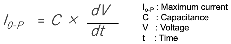
*24 The maximum current that can flow through the capacitor is expressed as the product of the pulse rise time (dV/dt) and the capacitance.
*25 Steep voltage variations over time may occur in motor drives, inverters, resonant circuits, snubber circuits, etc.
Please also note;
When high frequency current flows, the capacitor will self-heat. The upper limit of high frequency current is specified for each frequency. If you have any questions, please contact us.
Case 14 A Capacitor Suffered From Thermal Stress
(Thermal stress leads to self-ignition)
The film capacitor mounted on the board is overcoated with resin (Figure 31). The connection between the capacitor element and the lead wire sparked and the capacitor caught fire.

A overcoated capacitor on a substrate
What is the cause of the failure?
The capacitor was stressed by repeated expansion and contraction of the coated resin due to changes in ambient temperature.
As a result, the connection between the capacitor element and the lead wire was stressed and peeled off, and voltage was applied, causing a spark and the capacitor to fire (Figure 32).

The connection between the capacitor element
and the lead wire was stressed and peeled off

The connection between the capacitor element
and the lead wire was stressed and peeled off
How to do, what to do?
The coefficient of thermal expansion of the resin to be coated and the substrate should be fully taken into consideration. The amount of resin should be kept to a minimum.
Please also note;
Embedding, fixing, or coating capacitors with resin may cause unexpected failures. Also, if the capacitor resonates due to vibration, the leads or electrodes may break.
Case 15 Strange Sound Came From a Film Capacitor
(Dielectric vibration)
When I turned on the power, I heard strange sounds like "gee" or "beep" sound from the film capacitor.
What is the cause of the failure?
A film capacitor consists of an extremely thin plastic film wound up (wound element). Both ends of the element are secured by electrodes, but the film sections physically overlap each other and are not secured.
When voltage is applied to the capacitor, the Coulomb force acting between the electrodes causes the plastic film to mechanically vibrate, which may generate a buzzing sound*26.
This sound is especially high when there is distortion in the supply voltage or waveforms containing harmonic components.

Metalized film capacitor
*26 Metalized film vibrates under Coulomb forces.
How to do, what to do?
If the sound is a continuous oscillating sound, the capacitor is not at fault. The louder the capacitor, the longer the dimension between terminals or the capacitor with flat elements, the louder the sound. If the sound level exceeds the permissible range or if it is a sporadic popping sound, use an "anti-sound" type with a short dimension between terminals.
Please also note;
When an AC voltage is applied to a laminated ceramic capacitor, the capacitor itself may expand and contract, resulting in the circuit board vibrating like a loudspeaker in the plane direction. When the period of vibration matches the human audible frequency range (20 to 20 kHz), it is heard as sound. The expansion and contraction of the capacitor is caused by the "electrostriction effect*27" of dielectric ceramics, which is said to be difficult to counteract.
*27 Electrostriction (cf. magnetostriction) is a property of all electrical non-conductors, or dielectrics, that causes them to change their shape under the application of an electric field.
Appendix What's A Capacitor
Aluminum Electrolytic Capacitors Features and Structure
[Features]
Aluminum electrolytic capacitors are polarized, finite life capacitors based on electrochemical operating principles, called "chemical capacitors".
Aluminum electrolytic capacitors are widely used in DC circuits because of their advantages such as high volumetric efficiency (capacitance per unit volume), large capacitance of several thousand millifarads (mF), withstand large ripple currents, and high reliability.
When using aluminum electrolytic capacitors, it is necessary to take care that they have a larger leakage current, a wide tolerance range of capacitance, ±20%, a higher equivalent series resistance, and a finite life than other capacitors.
[Structure]
The type of aluminum electrolytic capacitors can be broadly classified into three types: wet type*28 using a liquid electrolyte for the cathode, solid type using conductive polymers, and hybrid type using both electrolyte and conductive polymers.
*28 We supply wet type aluminum capacitors.
The wet type aluminum electrolytic capacitor, the most commonly used type, consists of a capacitor element impregnated with electrolyte, connected to an external terminal, and sealed in a case. Figures 34 shows typical aluminum electrolytic capacitors and element structures.

Typical Al-capacitor Types

Typical Al-capacitor Types
The element of an aluminum electrolytic capacitor consists of two aluminum foils and a separator, typically wound as shown in Figure 35.
The aluminum foil is etched by electrochemical technologies, so it has a large surface area*29. There is an anode foil with a dielectric formed on its surface and a cathode foil as a counter electrode. Each foil is connected to an external terminal by a lead tab.
The separator prevents direct contact between the two aluminum foils and retains the electrolyte.
*29 The dielectric is the very thin anodic aluminum oxide on the highly etched 3D surface of the anode foil. The etched surface comprises billions of microscopic tunnels to increase the surface area in contact with the electrolyte.

Capacitor element of aluminum electrolytic capacitor
Metalized Film Capacitors Features and Structure
[Features]
Film capacitors have a thin plastic film as the dielectric. Film capacitors have no polarity, stable electrical performance, low self-inductance, low ESR, and high insulation resistance, making them excellent for use at high voltages and for voltage holding characteristics.
For this reason, they are widely used in power electronics applications such as DC link and snubber circuits in power supply circuits.
Typical film capacitance range is from 1nF to 100µF and covers from 50 V to 2 kV voltage range.
However, due to the relatively low relative dielectric constant of the dielectric film, it is difficult to reduce the size of the capacitor.
We have a lineup of film capacitors for AC and DC power electronics equipment.
[Structure]
Most film capacitors use metal foil or metalized layer for the inner electrodes. Two films cut into ribbons of a specified width are rolled to the required length according to the capacitance. Tin or other metal is sprayed onto both ends of the roll by thermal spraying to form a current collecting electrode (Figure 36).

Capacitor element of metalized film capacitor
Generally, metalized film capacitors with aluminum or other materials as electrodes, are widely used.
Compared to metal foil film capacitors, metalized film capacitors can be made smaller. In addition, if there is a defect in the dielectric, the metalized layer in that area evaporates, isolating the defective part*30 and allowing the capacitor to continue to operate with only a slight decrease in capacitance.
*30 This action is called self-healing, SH.
When current repeatedly flows into a defective part due to overvoltage or dielectric degradation, the capacitor continues to self-heal and loses capacitance. Generally, a capacitor is considered to have failed when its capacitance drops by 3% or more compared to its initial value.
Failure Modes of Capacitors
The probability that a failure will occur is called 'failure rate'. There are two types of failure rates: average failure rate and hazard rate (instantaneous failure rate).
Average failure rate is the total number of failures divided by the total operating hours.
Hazard rate is the "percentage of failures that occur within a unit period," and the unit is often %/hour. For components with a low failure rate, the unit is Fit (Failure in time: 10-9/hour).
The failure rate of capacitors can be divided into three regions by time and is represented by a bathtub curve as shown in Figure 37.
(1) Early failures*31 exhibits a shape where the failure rate decreases over time. The vast majority of capacitor's initial defects belong to those built into capacitors during processing.
(2) When capacitors containing early defects have been eliminated to a certain degree, the early failure rate becomes extremely small, and the failure rate exhibits a constant level over time. In this state, the failure distribution is close to an exponential distribution, and this is called the random failure period*32.
(3) Intrinsic failures (Wear-out)*33 are failures rooted in the durability of the materials comprising capacitors, connecting or sealing elements.
*31 This property of capacitor where the failure rate decreases over time can be used to perform screening known as "burn-in" where stress is applied for a short time in the stage before shipping to eliminate devices containing early defects.
*32 Most of the failures are due to capacitors containing relatively insignificant early defects that fail after a long time or random accident such as overvoltage.
*33 In this region, the failure rate increases with time until ultimately all the devices fail or suffer characteristic defects.

Bath-tub Curve
The length of this random failures period is the "useful life" of the capacitor.
In aluminum electrolytic capacitors, the electrolyte evaporates due to operating temperature and self-heating during use, resulting in failures such as capacitance reduction, increased tan δ and leakage current. Such failures can be avoided with preventive maintenance action such as replacing the capacitor.
For film capacitors, the typical failure mode is capacitance decrease due to self-healing, so it is possible to diagnose the life expectancy by understanding the capacitance change.
Conclusion
Capacitors fabricated with reliable technology and strictly controlled processes can enhance the performance and reliability of electronic circuits. The estimated failure rate of our aluminum electrolytic capacitors is about 0.3Fit, which is about 1/10 of that of general semiconductor devices.
Ensuring the performance, quality, reliability, and safety of devices developed and manufactured by our customers is only possible through collaboration between us and our customers.
We will continue our constant efforts to improve the quality, reliability, and safety of our capacitors, and we will label our products and documents with precautions and restrictions for use, and recommend products appropriate for their applications.
Customers are requested to select capacitors with quality and reliability that meet the requirements of their equipment, not to apply stress beyond the capacitor's capability when using the equipment, to implement safety design and safety measures in the equipment, and to fully evaluate the function, performance, quality, reliability, and safety of the capacitors before use. Please ensure that the capacitors are fully evaluated for function, performance, quality, reliability, and safety prior to use.
In this report, we have introduced some examples of problems that may occur with our capacitors so that they can be used with higher reliability. For specific precautions for each capacitor, please refer to the catalog or specification sheet. If you have any questions, please contact us.

Editorial supervision/Kazuyuki Iida
General Advisor, AIC tech Inc.
Born in the Tokyo area in 1956
M.S. of Sc, Sophia University, Tokyo, Japan. 1982
Over 35 years experience with knowledge on capacitor technology, i.e. R&D for high-performance capacitor and its materials, marketing activities at Hitachi Chemical Co, Ltd. and Hitachi AIC Inc. and Contributed articles on capacitors to public relations magazines, trade journals, and various handbooks.
Instructor of capacitor technology at the Technical Training Institute of Hitachi, Ltd. from 2005 to 2015.
General advisor to AIC tech Inc. from 2020.
- "Tantalum Electrolytic Capacitor"
The Electrochemical Society of Japan (ed.) Maruzen Handbook of Electrochemistry, 5th Edition, Chapter 15, Capacitors, Section 15.2.4 b (1998) - "Development Trend and Material Technology of Tantalum-Niobium Capacitors"
Technical Information Association of Japan Seminar June 2008 - Lead-Free Surface Mount Film Capacitors MMX-EC, MML-EC Series
Hitachi Chemical Technical ReportNo. 48. Product Introduction 2007 - "Film Capacitors for Electronic Devices"
Maruzen Capacitor Handbook, 5th Edition, Chapter 5, Film Capacitors, Section 5.2 (2009). - "Film capacitor MLC series for new energy"
Shinkobe Electric Co., Ltd. Shinkobe Technical Report Np. 22 (2012).
PDF Download