Electrolytic vs. Film Capacitors
- Application Case Studies -
Introduction
In power electronics, capacitors are essential devices for energy storage, filtering, decoupling, and other functions. However, there are many different types of capacitors, and even capacitors with the same capacitance and voltage rating can vary in performance. And the wrong choice of capacitor can lead to expensive overdesign and unreliable products.
This paper describes the features and functions of the various types of capacitors used in power electronics. In particular, we will compare aluminum electrolytic and metalized film capacitor types and explain what role each plays in different situations. Specifically, the construction of the various capacitor types, their suitability for power electronics, capacitance, ripple current ratings, transient overvoltage (spike voltage), safety specifications, and other characteristics will also be discussed in detail.
Contents
- Capacitors Introduction
- Comparison of Electrolytic vs. Film Capacitors
- Application Case Studies
- Motor Drives
- Renewable Energy System
- Servo Drivers
- Switching Mode Power Supplies (SMPS)
- Pulsed Power Supply
- Uninterruptible Power Supply (UPS)
- Traction Control System
- Conclusion
Capacitors Introduction
Electrolytic Capacitors
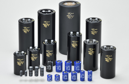
Electrolytic capacitors are polarized capacitors known for their high capacitance values relative to their size, often used in applications requiring significant energy storage, such as power supplies and audio equipment. They achieve high capacitance by using an electrolytic solution combined with an anode foil with a large surface area, separated from a cathode foil by a thin dielectric oxide layer. This construction enables them to store a considerable amount of charge in a compact form.
Film Capacitors
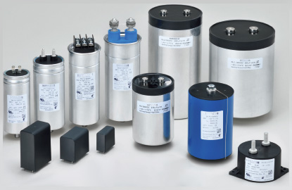
Film capacitors use a thin plastic film as the dielectric and a metalized electrode, typically aluminum, deposited onto the film's surface. The dielectric film, often polypropylene, is extremely thin (2–5 μm) and wound into a compact coil structure. Known for their high stability, these capacitors exhibit minimal capacitance change over temperature and frequency variations, low ESR (Equivalent Series Resistance), and low inductance, making them suitable for high-frequency applications.
Comparison of Electrolytic vs. Film Capacitors

Application Case Studies
This chapter presents applications of capacitors in typical equipment used for various power conversion applications.
Motor Drives
Motor drives are electronic devices that convert a fixed voltage from an AC power source into a variable voltage that controls motor torque and controls the speed of various motors in any system, from small pumps and motors in home appliances such as washing machines and air conditioners to large motors in industrial equipment.
Capacitors used in motor drives
The key role of capacitors in this application is to remove ripple current. Aluminum electrolytic capacitors are the most commonly used capacitors in DC link of motor drives, both single-phase and three-phase. Specifically, they are used as energy buffers to remove ripple currents in DC line and to keep the inverter running stably.

Block diagram of single phase motor drive

Block diagram of 3 phase motor drive
The ripple current in motor drive has two components: low-frequency ripple on the input side (50 Hz to 200 Hz) and high-frequency component from the inverter (typically 8 kHz to 20 kHz). For this reason, it is important to use capacitor with the appropriate capacitance and ESR characteristics for each ripple current.
How to select and use capacitors
Ripple current causes the capacitor to self-heat, and excessive ripple current will shorten the life of capacitor. Since aluminum electrolytic capacitors are finite life capacitors, measures should be taken to maximize their life. For example, placing the capacitors on printed circuit board in the coolest possible location, forced cooling, and mounting heat sinks on the capacitors are effective measures. Aluminum electrolytic capacitors are available with an improved internal structure to enhance heat dissipation. Combined, these measures can extend the life of capacitors by several times or more.
It is also necessary to specify minimum capacitance to ensure stable operation of the motor drive. It is also important to use products with low capacitor inductance (ESL), since ESL can cause voltage pulses.
High-voltage motor drives
For high-voltage motor drives with output voltages up to about 1,200V, multiple aluminum electrolytic capacitors can be used in series and parallel connection. However, care must be taken to balance the intermediate voltages between capacitors*01 . Therefore, voltage divider resistor must be connected in parallel with aluminum electrolytic capacitors to divide the voltage evenly*02.

Circuit topology of a three-phase power converter
of AC drive system with two electrolytic capacitors connected in series
*01 In a series connection of capacitors, the voltage across each capacitor is divided according to the ratio of the capacitor‘s insulation resistance (or the ratio of the capacitor’s leakage current). However, uneven balancing of the divided voltages reduces the overall efficiency of the equipment and shortens the life of the capacitors.
CLC/TR 50454:2008, Guide for the application of alminium electrolytic capacitors, CENELEC, Brüssel (2008)
*02 When converters are constantly connected to the main power supply, as in industrial equipment, the losses due to the voltage divider resistors cannot be ignored in terms of energy and cost. In addition, the voltage divider resistors are often located close to the capacitors as a heat source, posing a risk to the capacitors and other devices.
Our products suitable for motor drives
We provide 2, 3, and 4 terminal aluminum electrolytic capacitors with long life and high current ratings that can be mounted on printed circuit boards. We also offer lineup of capacitors with improved heat dissipation and heat sink friendly structures. For industrial motor drive applications, large screw terminal type aluminum electrolytic capacitors are available.

VFH Series - a high-reliability, long-life screw-terminal aluminum electrolytic capacitor designed for demanding power applications, offering up to 20,000-hour endurance at 85°C.
VGLR Series – a high-ripple-current, low-ESR screw-terminal aluminum electrolytic capacitor with improved heat dissipation and a 5,000-hour endurance rating at 105°C.
MLC Series – robust cylindrical metallized polypropylene film capacitors with large capacitance, segmented metallized film for high reliability, and optional UL 810 compliance, ideal for power inverters, chopper control, and charge–discharge applications.
Renewable Energy System
Since the beginning of this century, installed capacity of solar and wind power generation has grown dramatically on global scale. These renewable energy systems use high-power power conversion technologies, and inverters that are at the core of these systems must incorporate high-voltage, high-capacity capacitors.
Inverters for wind power and photovoltaic power generation are responsible for the function of converting DC current to AC current, but at the same time, they are required to improve the efficiency of power conversion and the stability and reliability of long-term operation. Therefore, the capacitors (DC link) that prevent the ripple current generated by the power conversion from flowing into the inverter must also be highly reliable.
Capacitors in renewable energy systems
Solar Inverters
Solar inverters are devices that efficiently convert DC power generated by solar panels into AC power that can be used in power grids and household systems*03 .
*03 Depending on the overall size of the power generation system, solar inverters have power ratings of up to about 3 kW for residential inverters, up to 10 kW for connected string inverters, and up to 500 kW for large central inverters.
Figure 4 shows basic configuration of a typical solar inverter. DC power from solar battery passes through EMI filter and is sent to boost converter, which then supplies power to inverter through capacitors in DC link. In other words, solar inverter acts as an interface between solar panels and power system. As shown in Figure 4, two power conversion processes take place inside the solar inverter.

Block diagram of solar power generator
Typical maximum output voltages for solar panels are 600V, 800V, and 1,000V. To cover this voltage range with aluminum electrolytic capacitors, a series connection of capacitors is required. However, when connecting aluminum electrolytic capacitors in series, it is important to balance the voltage at the center point between two series capacitors. On the other hand, the use of balancing resistors or other devices can cause significant reduction in efficiency.
DC link capacitors that generate enough energy for smooth voltage conversion in solar inverters are important. Depending on the power range, maximum allowable voltage, available space, lifetime requirements, and design cost, either aluminum electrolytic or film capacitors can be used. Both types are available from us*04 .
*04 The size of energy buffer is determined by the amount of energy that must be stored in the buffer. This is related to the power rating of the solar inverter and the duration of the mismatch between the power from the solar panels and the power to the distribution system. As a rule of thumb, if this duration is less than 1 second, film or aluminum capacitors can be used. If it is longer, other energy storage devices such as electric double layer capacitors (EDLCs) or batteries should be considered.
Wind Power Inverter
Unlike photovoltaic power generation, wind power generation has AC input, so the power is converted to DC once by ACDC converter and then sent to inverter.
Large-scale wind power generation systems are often installed offshore or in mountainous areas, so there is a demand for designs that require as few parts to be maintained or replaced as possible. In addition, because the no-load induced voltage of PMSG (permanent magnet synchronous generator) type generator increases in proportion to the wind turbine speed, there is a risk of DC voltage exceeding the rated voltage when the wind turbine speed increases due to gusts of wind or other factors. Traditionally, aluminum electrolytic capacitors were used as DC link capacitors connected in series, but because they require periodic maintenance and replacement and have low tolerance to overvoltage, large-capacity film capacitors are increasingly used in recent large wind power inverters.
AIC offers resin case type film capacitors with 2 and 4 wire lead terminals. For main inverter applications, we offer screw terminal type with case sizes up to Φ90mm x L268mm.

Block diagram of wind power generator

VG Series – a screw-terminal aluminum electrolytic capacitor offering 50% higher ripple current through its new heat-radiation construction, with a 2,000-hour endurance rating at 105°C.
VGR Series – a high-ripple-current screw-terminal aluminum electrolytic capacitor offering approximately 60% greater permissible ripple current than the VG series, with a 2,000-hour endurance rating at 105°C.
VGLR Series – a high-ripple-current, low-ESR screw-terminal aluminum electrolytic capacitor with improved heat dissipation and a 5,000-hour endurance rating at 105°C.
MKCP4 Series – resin-encased metallized polypropylene film capacitors for DC link applications, featuring UL94V-0 flame-retardant materials and reliable operation up to 1,100Vdc.
MKCP4T Series – resin-encased metallized polypropylene film capacitors for DC link circuits in high-humidity environments, featuring UL94V-0 flame-retardant materials and up to 105°C operating temperature.
MLC Series – robust cylindrical metallized polypropylene film capacitors with large capacitance, segmented metallized film for high reliability, and optional UL 810 compliance, ideal for power inverters, chopper control, and charge–discharge applications.
Servo Drivers
Servo driver is a device that controls inverter in response to feedback from motor to arbitrarily control state quantities such as motor speed, torque, and current*05, 06, 07. When motor performs work in response to load torque, the servo driver supplies the motor with enough energy to do the work it. Since energy is exchanged instantaneously, power (work rate) is controlled in real time. Therefore, servo driver consists of power conversion circuit and control unit. However, in recent years, power devices have become increasingly low-loss (lower on-voltage), and the energy efficiency of power conversion circuits exceeds 95%.
*05 https://www.ieice.org/~icd/
https://pwel.jp/
*06 Fujimoto et.al., Journal of RSJ, Vol.25 No.7, pp.1036~1039, 2007
https://www.jstage.jst.go.jp/article/jrsj1983/25/7/25_7_1036/_pdf
*07 Although the above configuration is common for servo drivers used in industrial applications, there are some that omit the converter circuit and use a battery as the DC power source. Some drivers do not have a position control function. There are also inexpensive simple drivers that use a linear amplifier instead of an inverter, an analog potentiometer instead of a rotary encoder, or an operational amplifier instead of a microcontroller. For servomotors with small output, servomotors and servo drivers are also available as an integrated unit.
Capacitors in servo drivers
Figure 6 shows the basic configuration of typical industrial servo driver. The AC input power is rectified in the converter circuit and converted to DC via capacitors in the DC link to supply power to the inverter.

Servo motor drive system
The most commonly used capacitor in the DC link of servo driver is aluminum electrolytic capacitor. They act as energy buffer to ensure stable operation of the switch-mode inverter that drives the motor as well as the motor drive, and as filter to remove high-frequency components.
Our products are suitable for servo drivers
We offer snap-in type aluminum electrolytic capacitors that have a long life and can handle high ripple currents. For industrial servo drivers, we offer large screw terminal type aluminum electrolytic capacitors.

ZL Series – snap-mount aluminum electrolytic capacitors designed for compactness and a 3,000-hour endurance at 105°C, offering reliable performance in general-purpose power applications.
VFLR Series – high-ripple-current screw-terminal aluminum electrolytic capacitors offering up to 20% more ripple current and a 5,000-hour endurance at 85°C.
VGR Series – a high-ripple-current screw-terminal aluminum electrolytic capacitor offering approximately 60% greater permissible ripple current than the VG series, with a 2,000-hour endurance rating at 105°C.
ZR2 Series – a higher-ripple-current snap-mount aluminum electrolytic capacitor with approximately 15% more ripple current than the ZR series and a 3,000-hour endurance at 105°C.
FXW Series – a screw-terminal aluminum electrolytic capacitor offering up to 35% higher capacitance (vs. FX2) through special etched foil and a 5,000-hour endurance at 85°C.
FXW2 Series – a screw-terminal aluminum electrolytic capacitor offering around 30% higher capacitance than the original FXW series, with a 5,000-hour endurance at 85°C.
Switching Mode Power Supplies (SMPS)
Switching mode power supplies (SMPS*08), also called switching mode DC regulated power supplies, are power conversion devices that supply DC power to power various electrical and electronic loads*09 .
Unlike linear power supplies that use a standard linear voltage regulation scheme, SMPS uses a semiconductor switching scheme to regulate the voltage of non-regulated signals. That is, a semiconductor switch such as a power MOSFET conducts current when it is on and interrupts current flow when it is off. The output is stabilized by controlling this on/off time ratio (duty ratio) with a feedback circuit.*10 Switching power supplies convert alternating current from commercial power sources into direct current and are widely used as compact, lightweight power supplies with low power consumption and high-power conversion efficiency.
SMPS consists of (1) input rectifier and filter (diode rectifier and capacitor filter), (2) high frequency switch (power transistor or MOSFET), (3) power transformer output rectifier, (4) filter (diode rectifier and capacitor filter), and (5) control circuit (comparator and pulse width modulator). (Figure 7).
*08 Switching Mode Power Supply
*09 https://electronicscoach.com/switch-mode-power-supply.html
*10 However, the switching on and off is performed at high speed, which is a characteristic that can easily generate EMI.

Block diagram of SMPS
Capacitors in SMPS
Switching mode power supplies have a variety of applications, and in recent years they have been increasingly used in server power supplies (Figure 8). Server power supplies consist of a PFC circuit and a stabilizing circuit using power MOSFETs, enabling high power density and high efficiency output.
Small and long-life aluminum electrolytic capacitors are used here as DC voltage smoothing and energy buffers at the output of PFC and regulated power supply circuits.

Server power supply capacitor applications ○
Our products suitable for switching mode power supplies
We offer small and long-life snap-in type aluminum electrolytic capacitors that have high ripple current rating.

ZL Series – snap-mount aluminum electrolytic capacitors designed for compactness and a 3,000-hour endurance at 105°C, offering reliable performance in general-purpose power applications.
HL Series – a miniaturized snap-in aluminum electrolytic capacitor offering up to 8,000-hour endurance at 105°C.
HU Series – a compact radial aluminum electrolytic capacitor with 2,000-hour endurance at 105°C, suitable for general-purpose high-voltage applications.
Pulsed Power Supply
Pulsed power supply is a device that outputs instantaneous high power for a short period of time (microseconds or nanoseconds) by turning the output on and off at the required timing, rather than continuously supplying power like an ordinary power supply. Pulse power supplies are applied to X-ray generators, welding machines, excimer lasers, ultraviolet light sources, high-frequency plasma torches, etc., and are installed in semiconductor manufacturing equipment, medical equipment, environment-related equipment, accelerators, etc.

Inverter type X-ray generator*11
*11 An inverter outputs alternating current with a frequency corresponding to the tube voltage, and a transformer boosts the voltage. The rectified high voltage is detected and fed back to the inverter to obtain a stable high voltage.

Arc welding machine*12
*12 An inverter outputs alternating current at a frequency corresponding to the welding current, and a high-frequency transformer boosts the voltage. The rectified high voltage is detected and fed back to the inverter to obtain a stable current.
Capacitors in pulsed power supplies
The role of capacitor in pulsed power supply is to buffer energy. An important parameter for this is large capacitance of capacitor. This is because the size of capacitance is directly related to the amount of electrical energy boost that the power supply can generate*13.
Also, in this application, charging and discharging is repeated, and the voltage drop across the capacitor during discharge must be taken care of. For complete discharge, film capacitors are advantageous. For discharges in the range of 30% to 40% of maximum operating voltage, aluminum electrolytic capacitors can be used.
*13 The inductance (ESL) of the capacitor is also important, since a large ESL may increase transient signal generation. For large screw terminal type capacitors, an ESL value of 13 nH or less is generally required.
Our products suitable for pulse power supplies
We offer 2 and 4 terminal snap-in capacitors with high capacitance, long life, and high heat dissipation design for mounting on printed circuit boards. For high-voltage industrial applications such as industrial welding machines, high-frequency plasma torches, and X-ray equipment, we recommend our screw terminal aluminum capacitors with high withstand voltage, high capacitance, and long life.

VFH Series - a high-reliability, long-life screw-terminal aluminum electrolytic capacitor designed for demanding power applications, offering up to 20,000-hour endurance at 85°C.
VGLR Series – a high-ripple-current, low-ESR screw-terminal aluminum electrolytic capacitor with improved heat dissipation and a 5,000-hour endurance rating at 105°C.
MLC Series – robust cylindrical metallized polypropylene film capacitors with large capacitance, segmented metallized film for high reliability, and optional UL 810 compliance, ideal for power inverters, chopper control, and charge–discharge applications.
VF Series – a screw-terminal aluminum electrolytic capacitor featuring 10% higher ripple current than the HCGF6A series and a 2,000-hour rating at 85°C.
HCGW2 Series – a screw-terminal aluminum electrolytic capacitor featuring approximately 20% higher capacitance than the HCGWA series, with a 2,000-hour endurance at 85°C.
HCGW3 Series – a high-capacitance, high-energy screw-terminal aluminum electrolytic capacitor offering about 30% more capacitance than the HCGW2 series, designed for momentary large energy demands (e.g., UPS, X-ray power) with a 2,000-hour rating at 70°C.
FXW Series – a screw-terminal aluminum electrolytic capacitor offering up to 35% higher capacitance (vs. FX2) through special etched foil and a 5,000-hour endurance at 85°C.
FXW2 Series – a screw-terminal aluminum electrolytic capacitor offering around 30% higher capacitance than the original FXW series, with a 5,000-hour endurance at 85°C.
Uninterruptible Power Supply(UPS)
UPS is a power supply used to maintain power in the event of a brief power failure or voltage drop. UPSs are buffered by batteries or capacitors until power is restored after a power failure or load fluctuation, and are available in offline and online types with varying power levels and maximum operating times during a power failure.
Capacitors in UPS
Aluminum electrolytic capacitors are often used as DC link capacitors in UPSs, both in online and offline systems.
UPS systems convert AC input voltage to DC voltage. The converted DC voltage provides DC power to the inverter while charging the battery. The inverter converts the DC voltage to AC voltage and supplies it to the load*14 . During normal operation, the battery and capacitor are charged, but the capacitor prevents ripple current from flowing into the battery, thereby contributing to battery longevity. They also serve to absorb voltage spikes that occur when the inverter turns DC off and on at high frequency.
When a brief power outage or voltage drop occurs, the battery discharges to provide power. However, since it is difficult for the battery to provide sufficient power instantaneously, the capacitor discharges to assist in the initial power supply. In this way, capacitors play an active role in UPSs both in normal operation and during power outages. Therefore, capacitors are required not only to have a large capacity to store more energy, but also to have durability against voltage spikes.
*14 Input voltage is typically three-phase 480 volts. Batteries and electric double layer capacitors may also be used.
")
Basic UPS configuration (example of constant inverter power supply system)*15
*15 Until the emergency power generation equipment is activated during a power outage (approx. 5 min.),The storage batteries are discharged to supply DC power. This is then converted to alternating current by an inverter to supply power.
Our products suitable for UPS
For UPS, we recommend screw terminal aluminum capacitors with high withstand voltage, large capacitance, and long life. All aluminum electrolytic capacitors, large or small, degrade over time. The most natural degradation is the drying of the electrolyte. Its rate is determined by the operating temperature and ripple current. For this reason, it is recommended that aluminum electrolytic capacitors be replaced periodically. *16
*16 If capacitors are used within the specified conditions, a typical replacement schedule is 10 years. Of course, replacement life also depends on the magnitude of ripple current, so please contact us when designing the long-term reliability of your UPS system.

FXW Series – a screw-terminal aluminum electrolytic capacitor offering up to 35% higher capacitance (vs. FX2) through special etched foil and a 5,000-hour endurance at 85°C.
FXW2 Series – a screw-terminal aluminum electrolytic capacitor offering around 30% higher capacitance than the original FXW series, with a 5,000-hour endurance at 85°C.
HCGW3 Series – a high-capacitance, high-energy screw-terminal aluminum electrolytic capacitor offering about 30% more capacitance than the HCGW2 series, designed for momentary large energy demands (e.g., UPS, X-ray power) with a 2,000-hour rating at 70°C.
VF Series – a screw-terminal aluminum electrolytic capacitor featuring 10% higher ripple current than the HCGF6A series and a 2,000-hour rating at 85°C.
VG Series – a screw-terminal aluminum electrolytic capacitor offering 50% higher ripple current through its new heat-radiation construction, with a 2,000-hour endurance rating at 105°C.
HCGWA Series – a high-capacitance, high-energy screw-terminal aluminum electrolytic capacitor, delivering up to 40% more capacitance than the HCGF6A series and supporting larger sizes up to φ121×283, with a 2,000-hour rating at 85°C.
Traction Control System
Traction control systems is a general term for systems that control the driving force of trains and automobiles. Electrical systems that support not only running, but also braking, lighting, and power supply are included in this category.
Electric motors used in electric railcars require properly controlled power. In the past, motors dissipated unused power through resistor banks, but now inverters are used to control the power to the electric motors by reducing heat generation.
Capacitors in traction control system
Capacitors are essential for inverters. When the inverter turns off the current, the current from the overhead wires flows to the capacitor and the capacitor stores electrical energy. When the inverter turns on the current, the current is supplied from the overhead line and the capacitor. The current flowing through the capacitor is the ripple current between the current from the overhead wires and when the inverter turns on/off.
Film capacitors are used for speed control of the large electric motors used to run electric railcars. This is due to the need for higher withstand voltage and lower losses.
Auxiliary power supplies for electric railcars require capacitors as energy buffers to ensure stable operation of the motors or auxiliary inverters that control the auxiliary power circuits, and aluminum electrolytic capacitors or film capacitors are used. Capacitors also act as a filter to prevent high-frequency components of the inverter from interfering with the main power input. Therefore, the most important point in selecting a capacitor is its ability to handle ripple current*17, 18 .

Block diagram of SIV system
*17 It must be able to handle high frequency ripple currents of 8 k to 20 kHz generated by the inverter.
*18 Aluminum electrolytic capacitors in traction should be mounted and placed in the coldest possible location to maximize their operating life. Forced cooling or mounting on heat sinks is required. To ensure stable operation of the drive, a minimum capacitance should be specified considering the operating temperature and frequency. The ESL of the capacitors must also be low, as it is a source of spike noise generation.
Our products suitable for traction control system
We offer not only high withstand voltage and low loss film capacitors, but also large screw terminal type aluminum electrolytic capacitors with excellent performance against ripple current and high heat dissipation for optimal cooling.

MLC Series – robust cylindrical metallized polypropylene film capacitors with large capacitance, segmented metallized film for high reliability, and optional UL 810 compliance, ideal for power inverters, chopper control, and charge–discharge applications.
MLC2 Series – a smaller-volume, metallized polypropylene film capacitor offering up to 15% more space savings than the MLC series, ideal for high-power inverter and chopper applications.
VF Series – a screw-terminal aluminum electrolytic capacitor featuring 10% higher ripple current than the HCGF6A series and a 2,000-hour rating at 85°C.
VFL Series – a screw-terminal aluminum electrolytic capacitor with about 10% higher ripple current than the FX2 series, providing a 5,000-hour endurance rating at 85°C.
Conclusion
This paper has introduced various applications in power electronics where our capacitors are at work.
The aluminum electrolytic and film capacitors we supply are suitable for DC links in motor drives, inverter systems for renewable energy, switching mode power supplies, and energy buffers in uninterruptible power supplies.
Capacitors are key devices in power electronics, and we offer capacitors designed and manufactured with controlled processes backed by solid technology. Our aluminum electrolytic capacitors have an estimated failure rate of approximately 0.3 Fit, which is about 1/10th that of typical semiconductor devices. Our customers and we work together to ensure the functionality, performance, quality, reliability, and safety of the devices they develop and manufacture.
We ask that our customers select capacitors with quality and reliability that meet the requirements of their equipment, that they do not apply stress beyond the capacitor's capability when using the capacitors, that they implement safety design and safety measures in their equipment, and that they fully evaluate the function, performance, quality, reliability and safety of the capacitors before use. Please implement safety design and safety measures for the equipment, and thoroughly evaluate the function, performance, quality, reliability, and safety before use. Please refer to our product catalogs and specifications for specific precautions for each capacitor.
Thank you very much for your understanding. If you have any questions, please feel free to contact us.

Editorial supervision/Kazuyuki Iida
General Advisor, AIC tech Inc.
Born in the Tokyo area in 1956
M.S. of Sc, Sophia University, Tokyo, Japan. 1982
Over 35 years experience with knowledge on capacitor technology, i.e. R&D for high-performance capacitor and its materials, marketing activities at Hitachi Chemical Co, Ltd. and Hitachi AIC Inc. and Contributed articles on capacitors to public relations magazines, trade journals, and various handbooks.
Instructor of capacitor technology at the Technical Training Institute of Hitachi, Ltd. from 2005 to 2015.
General advisor to AIC tech Inc. from 2020.
- "Tantalum Electrolytic Capacitor"
The Electrochemical Society of Japan (ed.) Maruzen Handbook of Electrochemistry, 5th Edition, Chapter 15, Capacitors, Section 15.2.4 b (1998) - "Development Trend and Material Technology of Tantalum-Niobium Capacitors"
Technical Information Association of Japan Seminar June 2008 - Lead-Free Surface Mount Film Capacitors MMX-EC, MML-EC Series
Hitachi Chemical Technical ReportNo. 48. Product Introduction 2007 - "Film Capacitors for Electronic Devices"
Maruzen Capacitor Handbook, 5th Edition, Chapter 5, Film Capacitors, Section 5.2 (2009). - "Film capacitor MLC series for new energy"
Shinkobe Electric Co., Ltd. Shinkobe Technical Report Np. 22 (2012).
PDF Download