Capacitors in Power Electronics: A Simple Selection Guide
Introduction
In power electronics, capacitors are essential devices for energy storage, filtering, decoupling, and other functions. However, there are many different types of capacitors, and even capacitors with the same capacitance and voltage rating can vary in performance. And the wrong choice of capacitor can lead to expensive overdesign and unreliable products.
This paper describes the features and functions of the various types of capacitors used in power electronics. In particular, we will compare aluminum electrolytic and metalized film capacitor types and explain what role each plays in different situations. Specifically, the construction of the various capacitor types, their suitability for power electronics, capacitance, ripple current ratings, transient overvoltage (spike voltage), safety specifications, and other characteristics will also be discussed in detail.
Contents
- Capacitors in Power Electronics
- Capactior Selection Guide
- Key Considerations for Selecting Capacitors
- FAQs
Capacitors in Power Electronics
Capacitors are Key Devices in Power Electronics
Passive components have a significant impact on the performance, cost, and size of power electronic systems. Capacitors, in particular, play a key role in all of the power transformations shown in Figure 15. For example, in the AC motor drive system shown in Figure 1, capacitors are used everywhere from input, through power conversion, to output. Capacitors are key devices in power electronics.

Block diagram of motor drive and capacitors
EMI filters
Capacitors are also widely used in power line EMI filters. Polypropylene capacitors corresponding to the safety standards for withstanding 4kV and 2.5kV are designated as "X1" and "X2", respectively, and have a capacity of several μF to meet EMI standards. Capacitors that attenuate common mode emissions from line to ground are "Y1" type with 8kV rating and "Y2" type with 5kV rating. These capacitors are primarily film capacitors, and their low ESL characteristics allow them to maintain high self-resonance.
Snubber
Capacitors can be used to intentionally slow down the switching waveform to reduce stress on semiconductors caused by EMI. This application requires the ability to withstand high voltage pulses (dV/dt) and voltage variations due to excessive RMS current. Film capacitors made of polypropylene are effective for this purpose (Figure 2).

Snubber network and capacitors
DC link capacitor
DC link means the connection between rectifier or ACDC converter and inverter, and is the system in which DC is supplied to the inverter. The capacitor used here is called DC link capacitor (Figure 3).
DC link capacitors are used as energy storage devices that smooth and stabilize the DC voltage and balance the load*01. In equipment with batteries such as electric vehicles and solar power generation, DC link capacitors are placed in parallel with the batteries. It serves to keep the voltage stable. DC link capacitors also help protect the inverter network from momentary voltage spikes, surges, and EMI. Noise is the result of pulsed inverter current and stray inductance on the DC bus.

DC link capacitor on various power conversion
*01 In the DC link of inverters for 3-phase motor drives, capacitor capacitance can be reduced to values of 7 to 10 μF per 1 kVA (approximately 400 V) of inverter power by using lower ESR capacitors, proper EMI filter design, and improved inverter control performance. For example, a motor with an output of 100 kW can be installed. For example, a drive inverter for an electric vehicle with a motor of 100 kW output would use a capacitor with a capacitance of 700 to 1000 μF.
Martin März et.al., CIPS 2010, March, 16 - 18, 2010, Nuremberg/Germany
Power Filters
In inverters and motor drives, capacitors are placed at the output to remove high ripple currents and prevent high dV/dt levels from causing stress and EMI (Figure 4). Since AC current is output here, a non-polarized capacitor is required. Aluminum electrolytic capacitors cannot be used. In addition, the operating environment is often harsh, requiring the voltage withstand and ripple resistance performance of polypropylene film capacitors.
")
Output filter capacitor at brushless motor (BLDC)
Capacitor Requirements in Power Electronics
The basic applications of capacitors in power electronics include energy storage, buffering, filtering, decoupling, and EMI protection. Capacitors are responsible for supplying energy and suppressing ripple current in the current by taking advantage of their charging and discharging functions (Figure 5). However, power electronics equipment has various requirements for capacitors, such as output energy magnitude, size, reliability level, operating environment, and allowable cost, as shown in Figure 6.

General capacitor requirements

Capacitor Requirements in Power Electronics
One of the challenges in power electronics is to improve power conversion efficiency. This is driving the development of new systems and components. The trend toward the use of wide bandgap (WBG) semiconductors (e.g., SiC *02 and GaN *03) in place of today's Si-based semiconductors is typical. This trend is changing the requirements for capacitors used in power electronics. These include low loss performance with high ripple current rejection even at higher switching frequencies, high withstand voltage performance for high operating voltages such as GaN (~650V) and SiC (~1,700V), and heat and weather resistance for stable use at high temperatures such as 125°C and 150°C.
Solutions that can achieve these requirements with current technology include multilayer ceramic capacitors, aluminum electrolytic capacitors, and evaporated-electrode film capacitors. Since capacitor characteristics are highly dependent on the properties of dielectric and capacitors are limited by the electric field in which they can operate continuously, each capacitor is segregated by energy density (Figure 7) *04. From this relationship, aluminum electrolytic capacitors appear to be the best capacitors. However, other capacitors also have advantages when factors such as operating temperature and equivalent series resistance are taken into account. The characteristics and performance of each capacitor are explained in next section.

Practical electric field strength, relative permittivity, and energy density of each dielectric *04
Al2O3 : aluminum oxide(Al electrolytic)
BOPP : Biaxial Oriented Polypropylene (Film)
TiO2 : Titan oxide(Class Ⅰ ceramic)
SrTiO3 : Strontium titan oxide(Class Ⅱ ceramic)
*02 SiC : Silicon carbide
*03 GaN : Gallium nitride
*04 Martin März et.al., CIPS 2010, March, 16 - 18, 2010, Nuremberg/Germany
Capactior Selection Guide
Comparison Chart
Key Points for Selecting a Capacitor
With today's technology, no capacitor can perfectly meet the requirements of system. Therefore, when selecting capacitor, it is necessary to consider the characteristics of each capacitor shown in Table 1. We are a specialized manufacturer of aluminum electrolytic capacitors and film capacitors, so please contact us for help in selecting the right capacitor.

Aluminum Electrolytic Capacitors
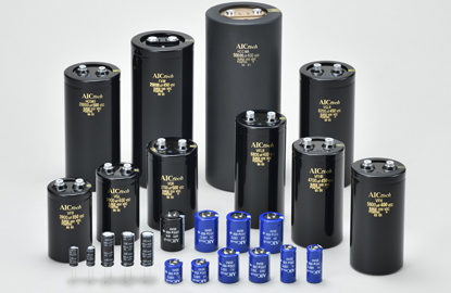
Aluminum electrolytic capacitors have a higher capacitance per unit volume, higher energy volume density (up to about 1 J/cm3), and a price advantage compared to other capacitors due to the specific structure of the element. In power electronics, a type of structure is used in which anode foil consisting of dielectric and electrode with large specific surface area is wound together with separator and cathode foil and impregnated with electrolyte (Figure 8).
")
Electrolytic capacitor
(appearance and element construction)
")
Electrolytic capacitor
(appearance and element construction)
Features
The type using electrolyte is not suitable for high-frequency applications such as EMI filters because ESR becomes larger at lower temperatures. Also, operating temperatures above 105°C are not practical when the rated voltage exceeds 350V. Solid conductive polymers in combination with electrolyte are available, but it cannot be used at high voltages exceeding 350V. With aluminum electrolytic capacitors, there is a trade-off between operating temperature range and ESR, and current technology makes it difficult to optimize these parameters simultaneously (Figure 9). Therefore, when using aluminum electrolytic capacitors, the design must take these factors into account.
")
ESR vs. frequency by temperature of electrolytic capacitor (Type VGR 400V 4,700μF)
AIC Tech Aluminum Electrolytic Capacitors
AIC Tech Inc.'s Aluminum Electrolytic Capacitors offer a comprehensive range of high-performance solutions for power electronics applications, including screw terminal, snap mount, and radial types. These capacitors are designed to operate within a wide temperature range of -40°C to +105°C, with capacitance values spanning from 8.2µF to 680,000µF. They offer useful lifetimes ranging from 4,000 to 20,000 hours.
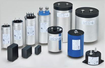
Metalized Film Capacitors
Metalized Film capacitor is a capacitor that uses plastic film as dielectric and metalized electrode made of aluminum or other material. As shown in Figure 10, the capacitor element is made by winding up a pair of films with metalized electrodes formed on them. It has stable capacitance with respect to temperature and frequency, high withstand voltage, low ESR, and low inductance*05 .
*05 The first capacitor was made in 1933 by Siemens of Germany, which wound polystyrene film together with aluminum foil. Today, capacitors are available in a variety of films, including polyester (Mylar), polystyrene, polypropylene, polycarbonate, and Teflon, covering a capacitance range from 5pF to several hundred uF.
Metalized electrodes are formed very thinly on one or both sides of the film. The film is mainly polypropylene, which is processed into very thin film of 2 to 5 μm by biaxial stretching.

Construction of metalized film capacitor and winding

Construction of metalized film capacitor and winding
Features
Metalized Film capacitors are non-polarized and can be used in AC circuits. They also have a longer life span, higher reliability, and slower aging than other capacitors, and their low ESR and ESL values and very low loss coefficient are also significant features. They can withstand kilovolt-class voltages and can also supply very high surge current pulses*06 .
*06 Power film capacitors capable of withstanding reactive power of 200 volt-amperes or more are also available. These are used in power electronics equipment, X-ray generators, pulsed lasers, etc. Low power types are used in decoupling capacitors, filters, and A/D converters. They are also used in capacitors for safety standards, EMI, fluorescent lamp ballasts, snubber capacitors, etc.
Metalized film capacitors offer the most balanced characteristics for the requirements of high voltage DC links, including withstand voltage, ESR, temperature range including low temperature, and durability. Although film capacitors have a lower relative dielectric constant than the dielectric of aluminum electrolytic capacitors, as shown in Figure 10, they are a promising solution in power electronics due to their high operating voltage. However, film capacitors with capacitance ranging from several hundred to 1000 μF occupy a volume of 1 to 2 liters, and as by far the largest component in an inverter, they determine the volume of the inverter. This makes low energy density a major challenge.
AIC Tech Plastic Film Capacitors
AIC Tech Inc.'s Plastic Film Capacitors for power electronics are designed to provide reliable and efficient solutions across various demanding applications. These capacitors operate within a temperature range of -40°C to +105°C, with rated voltages from 450V to 2,200V and capacitance values spanning from 1µF to 5,000µF. Available in both aluminum and resin encased types, they cater to standard, high-ripple current, and humidity-resistant needs, with options for standard, small-sized, and high-reliability products.
Multilayered Ceramic Capacitors (MLCC)
Multilayered ceramic capacitors are capacitors consisting of dielectric ceramic layers stacked together with electrodes, and are used in a wide variety of electronic circuits with capacitance ranging from 1 nF to a maximum of 1,000 µF.

MLCC outlook
Features
Multilayered ceramic capacitors are compact, capable of high AC currents and operating temperatures approaching 200°C. However, high withstand voltage specifications are suitable for power electronics. The capacitance can be as small as several tens of μF (500V), and to obtain a large capacitance, it is necessary to use a large number of members and connect them in parallel, which increases the cost. In addition, the capacitance varies with DC voltage, and attention must be paid to the resistance to stress and shock. In recent years, products resistant to mechanical stress have been developed and are spreading, especially in automotive equipment.
Key Considerations for Selecting Capacitors
Electrolytic vs. Film
Film capacitors have higher withstand voltage
Capacitors using polypropylene film have maximum withstand voltage of several kV. The rated voltage of aluminum electrolytic capacitors is limited by the thickness of oxide film and the properties of electrolyte, with upper limit of around 600 to 700V.
Film capacitors have well-balanced characteristics
Film capacitors have low capacitance variation with temperature, low heat generation due to ripple current, a short current path due to the electrode structure*07, and low ESL, allowing them to be used over wide frequency range, typically up to several MHz. Aluminum electrolytic capacitors have high dielectric loss, high ESR due to their structure of complex pores filled with ion-conductive electrolyte, and capacitance changes with temperature and frequency*08.
This limits the ripple current rejection capability of aluminum electrolytic capacitors. Furthermore, chemical reactions of the electrolyte with other materials cause changes in electrical characteristics over time, resulting in high failure rate after the end of life. Therefore, life calculations based on the operating profile of power electronic system are required.
*07 https://www.aictech-inc.com/information/capacitor_troubleshooting01.html
*08 https://www.aictech-inc.com/information/capacitor_foundation03.html
Aluminum electrolytic capacitors are smaller and have the highest energy density
When selecting a capacitor, not only performance but also component size is important. Aluminum electrolytic capacitors are smaller and have higher mounting efficiency than film capacitors; a 600V 1,000µF aluminum electrolytic capacitor is approximately 1/3 the volume of a film capacitor of the same rating (Table 2)*09
*09 The "Faraday" , also derived from Michael Faraday, is a unit of electric charge.

*10 The energy E stored in a capacitor is proportional to the square of its capacitance and voltage.It is obtained by E= C×V2/2.
Aluminum electrolytic capacitors have the advantage in price. But…
Price is also an important factor. Comparing film capacitors and aluminum electrolytic capacitors of the same rating, there is a cost difference of several times or more, and when considering component cost alone, aluminum electrolytic capacitors have the advantage*11 .
However, aluminum electrolytic capacitors may require additional circuits such as voltage dividing resistors and protection resistors. Film capacitors require few such external components. To extend the life of aluminum electrolytic capacitors and to ensure stable use, water-cooling mechanisms are sometimes provided.
Many factors must be considered when selecting capacitors, including characteristics, reliability, size, and cost. Therefore, it is extremely important to select a knowledgeable and experienced supplier and to take advantage of their expertise from the very beginning of the design process. We are a specialized manufacturer of capacitors for power electronics applications.
*11 This is a comparison on a major electronic components e-commerce site. Even if the ratings are the same, the price difference varies depending on quantity and specifications.
Difference in Failure Mode
Power electronic systems use a variety of devices, but capacitors are the second most critical device after semiconductors*12, and therefore capacitors must have higher reliability.
*12 S. Yang et.al., “An Industry-Based Survey of Reliability in Power Electric Covertors”, IEEE Transactions on Industry Applications, Vol.47, 1441, 2011.
With proper derating, the theoretical failure rates of aluminum electrolytic capacitors and film capacitors are comparable. However, depending on the operating environment, such as overload or high temperature, there is a risk of rapid wear failure leading to destructive failure*13 . Film capacitors can tolerate twice the rated voltage for a limited time. If abnormalities such as insulation breakdown or excessive current pulses (high dU/dt) occur in the film capacitor, the contact points of the deposition and current collecting electrodes will be damaged, causing a decrease in capacity or an open failure. However, when current is concentrated at the fault location, a plasma arc is generated to electrically disconnect the fault location and resolve the short circuit (self-healing). On the other hand, this may not work depending on the size and number of fault locations, and can lead to destructive failures if the film carbonizes and carbon deposits or if the overlapping films are damaged.
*13 In actual applications where voltage surges due to inductive loads or lightning strikes may occur, their failure rates may be different.
Aluminum electrolytic capacitors can only withstand an overvoltage of 120% of their rated voltage. If excessive stress is applied to aluminum electrolytic capacitors, they can short-circuit and damage the case or sealing, leak electrolyte and damage other components, or short-circuit the wiring pattern. If the dielectric of aluminum electrolytic capacitor is degraded and damaged, it will short-circuit, open, or somewhere in between, ultimately it can increase leakage current. If the aluminum electrolytic capacitor overheats and current continues to flow, the internal temperature rises above the boiling point of electrolyte, the internal pressure causes pressure valve to open, the electrolyte leaks, and the element may dry up.

Electrolytic or Film, Case Study in AC-DC Converter (Fault Ride-Through*14
*14 A sudden drop in the voltage level of the grid or a disturbance that causes a change in frequency may occur. The ability of the power supply to continue operation without stopping during such disturbances is called Fault Ride Through (FRT).
https://www.iee.jp/pes/termb_038/
Consider an AC-DC converter with power factor corrected front end, 90% efficiency, 1kW, and nominal 400V internal DC bus voltage as an example (Figure 12).

Fault ride through using electrolytic capacitor
When the capacitor is used as an energy buffer
When a momentary power failure occurs and the voltage level drops sharply, the capacitors on the DC bus release energy to support the converter so that it can continue to produce power. In other words, the capacitor acts as an energy buffer.
When a t- second power failure occurs and the converter voltage drops from Vn to Vd, the capacitor supplies the converter with the energy ΔP expressed in equation (1). This energy is equal to the product of the converter's output power Po and time t divided by the efficiency η (Equation (2)) *15 .
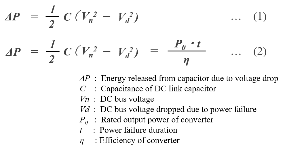
*15 https://www.analog.com/jp/technical-articles/replace-batteries-in-power-ride-through-applications-with-robust-supercaps.html
FRTs are important for renewable energy sources, many of which are connected to the grid by a PCS (Power Conditioner System). https://www.iee.jp/pes/termb_038/
Using the assumptions shown in Figure 1-8, 15, 16 (90% efficiency, 1 kW output, and nominal 400 V internal DC bus voltage), we calculate the capacitance appropriate for this application to be 634 μF.
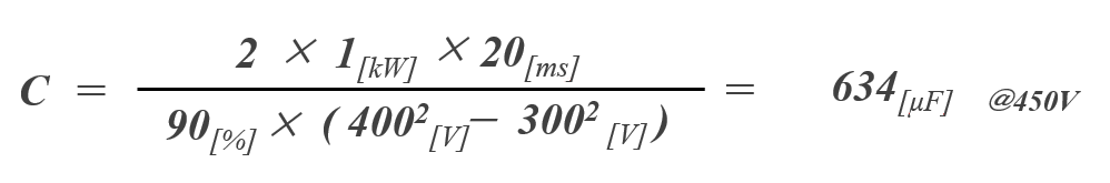
If our snap-in aluminum electrolytic capacitor HU type rated 450V 680μF is selected for this application, its volume is approximately 35cm3 (Φ30 x L50). If we substitute our film capacitor MKCP4 type to obtain the same capacitance, seven capacitors would be required in parallel, and the total volume would be 155cm3 (about 5 times larger) *16 . In other words, for this application, it is effective to select an aluminum electrolytic capacitor with high volumetric energy.
*16 Film capacitor ratings and single unit sizes areRated 700V 100μF, T60×H45×L57.5, The film capacitor is calculated as follows.
When using a capacitor as a ripple filter
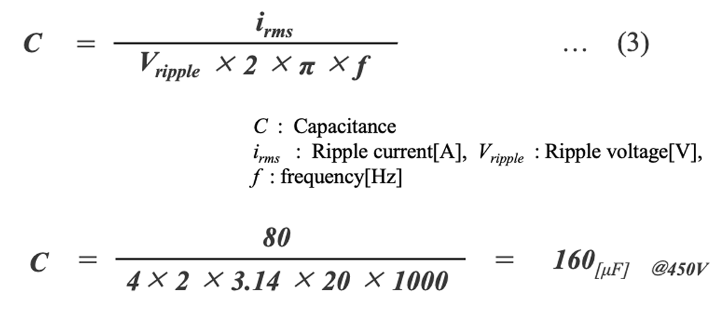
Next, consider the selection of a capacitor to be used to minimize the ripple voltage on 400VDC bus. The capacitance of capacitor can be approximated by Equation (3). For example, assuming converter frequency of 20 kHz, maximum ripple voltage of 4 Vrms, and ripple current of 80 A rms, the required capacitance is approximately 160 μF*17 。
*17 https://www.ti.com/lit/an/slta055/slta055.pdf
A rule of thumb for such applications is to use a ripple current of 20 mA per 1 µF capacitance, which is roughly consistent with the present results.
As candidates for capacitors for this application, we consider ZR type snap-in aluminum electrolytic capacitor rated 450V 180µF and MKCP4 type plastic case film capacitor rated 700V 80µF (Figure 13, Table 4).
, MKCP4 (Right)")
Type ZR (Left), MKCP4 (Right)
ZR type is considerably smaller than MKCP4 type, but it has lower allowable ripple current, about 1/10 of that of MKCP4 even after taking temperature and frequency compensation into account. Therefore, about 34 capacitors must be used in parallel to handle ripple current of 80Arms. In this case, the total capacitance is 6,120µF and the volume is approximately 748cm3, making it not an effective choice in terms of circuit miniaturization.
If MKCP4 type is selected, it is estimated that five capacitors can be used in parallel, and the total volume can be smaller than if ZR type is used *18 . Also, since ESR of MKCP4 is at the level of a few mΩ, losses can be reduced.
*18 The total volume when using 5 pieces of MKCP4 700V 80µF is 605cm3.

In selecting capacitor, the cost may be more important than physical volume or loss. Cost per energy*19 and cost per ripple current*20 as criteria for evaluating cost, the value of capacitor selected will depend on the requirements of application. The ratio of two costs may remain the same, although the absolute value of cost may go down when the volume used is higher.
*19 The unit cost of a capacitor divided by the electrical energy CV2/2[Joule] stored when the rated voltage is applied.The unit cost is based on cost data from a major distributor.
*20 The unit cost of the capacitor divided by the rated ripple current. Unit prices are based on cost data from a major distributor.
FAQs
What are the differences between power electronics and electronics?
Power electronics is a subfield of electrical engineering that deals with the design, control, and conversion of electrical power from one form to another. It involves the use of solid-state electronics, such as transistors and diodes, to control and manipulate high-power electrical energy.
Large amounts of power cannot be used as is, so it must be converted into usable form and controlled. Power electronics is the technology that makes this possible. In other words, it changes the form of electric power, converting electrical energy into kinetic and thermal energy for use (Table 5). *21, 22
*21 M. Morimoto, The visual encyclopedia of power electronics, Ohmsha

For example, electric vehicles run on batteries that spin motors, and power electronics technology is used to convert the DC power of the batteries into AC power that can be used for the motors, thereby converting the electrical energy in the batteries into kinetic energy for the motors. In other words, power electronics plays a role in changing and controlling the form of electric power (Figure 14).

Electrical Configuration of Electric Vehicles*23
What does "changing the form" mean in electric power?
Power electronics is a technology that uses electrical energy by changing the form of electric power. Changing the form of electric power is called power conversion. There are four basic power conversion types shown in Figure 15.

Four power conversion types*24

Four power conversion types*24
*24 While DC power is determined by the magnitude of voltage and current, AC power has complex factors such as frequency, phase, and number of phases as well as voltage and current.
What are the devices used in power electronics?
Power electronics is a technology that enables efficient conversion and flexible control of electrical energy. A variety of devices are used in this technology (Figure 16). In industrial equipment where power electronics is used, operating life is also important*25 and these devices are required to have an expected life of 10 to 20 years.

Devices used in power electronics
*25 There are design target lifetimes of 5 to 20 years (40,000 hours of full power operation) for industrial motor drives, 20 years (120,000 hours) for wind turbines, and 30 years (90,000 to 13 hours) for large photovoltaic plants . The target design life for large solar power plants is 30 years (90,000 to 13 hours).Huai Wang, IECON 2016 Tutorial October 24, 2016, Florence, Italy
*26 For Power Devices, IGBTs, MOSFETs, GTOs, and Thyristors, etc, They are used differently in terms of voltage-current (output) and operating speed (switching frequency).

Editorial supervision/Kazuyuki Iida
General Advisor, AIC tech Inc.
Born in the Tokyo area in 1956
M.S. of Sc, Sophia University, Tokyo, Japan. 1982
Over 35 years experience with knowledge on capacitor technology, i.e. R&D for high-performance capacitor and its materials, marketing activities at Hitachi Chemical Co, Ltd. and Hitachi AIC Inc. and Contributed articles on capacitors to public relations magazines, trade journals, and various handbooks.
Instructor of capacitor technology at the Technical Training Institute of Hitachi, Ltd. from 2005 to 2015.
General advisor to AIC tech Inc. from 2020.
- "Tantalum Electrolytic Capacitor"
The Electrochemical Society of Japan (ed.) Maruzen Handbook of Electrochemistry, 5th Edition, Chapter 15, Capacitors, Section 15.2.4 b (1998) - "Development Trend and Material Technology of Tantalum-Niobium Capacitors"
Technical Information Association of Japan Seminar June 2008 - Lead-Free Surface Mount Film Capacitors MMX-EC, MML-EC Series
Hitachi Chemical Technical ReportNo. 48. Product Introduction 2007 - "Film Capacitors for Electronic Devices"
Maruzen Capacitor Handbook, 5th Edition, Chapter 5, Film Capacitors, Section 5.2 (2009). - "Film capacitor MLC series for new energy"
Shinkobe Electric Co., Ltd. Shinkobe Technical Report Np. 22 (2012).
PDF Download