Capacitor Leakage Current Explained:
Characteristics & More
Contents
DC LEAKAGE CURRENT
- DC current through a capacitor
- Characteristics of Leakage Current
- Leakage Current of Aluminum Electrolytic Capacitors
- Leakage Current Summary
Leakage current is an electrical current that leaks from insulated areas in a circuit where current does not normally flow. Leakage current can cause problems such as circuit malfunctions, increased power consumption, and heat generation. Leakage current is a major problem in semiconductors consisting of minute circuits and elements*01. Capacitors also have leakage current. However, this includes not only the current that passes through the dielectric, which is an insulator, but also the current caused by dielectric polarization. In addition, when the insulation between the terminals is degraded by humidity or foreign matter adhering to the terminals, current may flow between the electrode terminals, bypassing the dielectric. This chapter explains the mechanism and properties of leakage currents and the precautions that should be taken.
*01 The leakage current of MOS transistors includes,
- Diffusion current from drain to source (sub-threshold current)
- Tunneling current from gate to source and drain (gate tunneling current)
- Junction leakage current
(GIDL: Gate Induced Drain Leakage) that flows from the drain to the substrate
DC current through a capacitor
Insulation resistance and leakage current
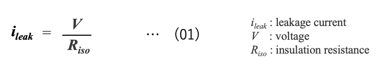
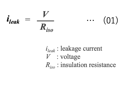
There are two parameters that describe the insulation properties of a capacitor: "insulation resistance" (Riso) and "leakage current" (ileak). The former is used for film and ceramic capacitors with very low leakage current, while the latter is used for electrolytic capacitors with high leakage current. The relationship between leakage current and insulation resistance can be expressed by the following simple equation*02 .
Leakage current can be regarded as an insulation resistance (IR) connected in parallel to the capacitance (Figure 1) and is therefore sometimes referred to as resistance (leakage resistance) rather than current.

Schematic diagram of capacitance and insulation resistance
*02 The relationship between applied voltage V, insulation resistance Riso and leakage current ileak is expressed as the following equation, V = ileak × Riso
Dc current through an ideal capacitor
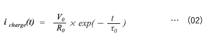
When an ideal capacitor C0 is charged from power supply V0 through external resistor R0 (Figure 2), the charging current icharge(t) decreases with time and the voltage v(t) across the capacitor terminals increases exponentially (Figure 3)

An ideal capacitor is charged through external resistor

Voltage, current versus time during capacitor charging
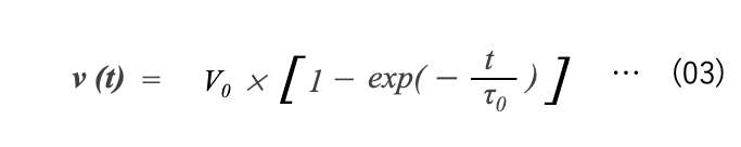
The charging current icharge(t) and the charging voltage v(t) are expressed by equations (02) and (03), respectively*03, where is the ratio between the supply voltage V0 and the resistance R0 at the start of charging (t=0).
*03 This formula represents the charging current and charging voltage of a capacitor in an RC circuit.
Charging continues until v(t) = V0 . τ0 is the product of resistance and capacitance and is called the time constant (Equation (04)) *04 .
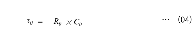
*04 The time constant is a measure of the speed of transients during charging and the time it takes to reach equilibrium.
If R0 is at the kilo-ohm (kΩ) and C0 is at the microfarad (μF) level, τ0 is on the order of milliseconds (ms). At this time (t = τ0) the voltage is 63.2% of equilibrium, i.e., v(t) = 0.632×V0. The time for v(t) to reach V0 can be calculated using equation (05), a variant of equation (03). At three times the time constant (t = 3τ0 ), the voltage is approximately 95% of V0.

In the cases of t = 5τ0 and t = 10τ0, the voltages can be calculated by equation (06) and (07). Therefore, The charging voltage is expected to reach almost the set voltage in about 5 to 10 times the time constant. At the same time, the current will be reduced to a negligible level.

Dc current through a real capacitor
Figure 4 shows the current behavior when a 1kΩ series resistor is connected to our aluminum electrolytic capacitor (4700µF rated capacitance) and the rated DC voltage is applied*05. A large current flows immediately after the start of charging, but it appears to decrease instantaneously and remain constant.
*05 The time constant of this RC circuit is 4700μF x 1kΩ = 4.7s.

DC current through type GXR capacitor*06
*06 The data was measured using a digital recorder with a sampling speed of 500 ms.
Replacing the current scale (vertical axis) in Figure 4 with a logarithm, we can see that the current decreases significantly for several tens of seconds after the start of charging, and then the current decreases slowly (Figure 4a).

DC current through type GXR capacitor
(The vertical scale in Figure 4 is rewritten in logarithm.)
When the time axis (horizontal axis) of Figure 4a is set to logarithmic scale, an inflection point in the plot appears around 35 seconds*07. Thereafter, the current progressively decreases linearly over 1000 seconds (about 17 minutes) (Figure 4b).
*07 In this case, the time of about 35 seconds is about 7.4 times the time constant of this charging circuit (4.7s).

DC current through type GXR capacitor*08
(The horizontal scale in Figure 4a is rewritten in logarithm.)
*08 The currents below 1 µA show fluctuations in measurement due to the fact that the measurement range was fixed at 100 mA.
This gradual decrease in current over tens to hundreds of seconds is also seen in other capacitors. Figure 5 shows data on the relationship between DC current and time when a ceramic capacitor is charged*09. The same behavior can be seen with ceramic capacitors, which have smaller capacitance than aluminum electrolytic capacitors.
*09 Alexander Teverovsky
NASA Electronic Parts and Packaging (NEPP) Program, Screening Techniques for Ceramic Capacitors with Microcracks, Part II. Leakage and Absorption Currents and Voltages in Ceramic Capacitors 2013

DC current through various ceramic capacitors
*10 Figure 5 shows data for ceramic capacitors with various temperature characteristics. The symbols in the figure are names according to the EIA standard (EIA-198). Each is defined as follows
X7R: Capacitance change within ±15% from -55 to +125°C
X5R: Capacitance change within ±15% in -55 to +85°C
NP0: Temperature coefficient within 0±30ppm/℃ in -55 to 150℃.
absorption current
The slow, linear, gradual decrease in current with time during charging a capacitor can be explained as the absorption of charge by the dielectric.
As described in Chapter 2, Impedance, actual capacitors have not only capacitance but also parasitic resistance and inductance in series or parallel (Figure 6)*11. Dielectrics also exhibit various behaviors in response to external electric fields. Dielectrics contain electrically polarized dipoles*12 and dipoles are oriented according to the strength of the electric field. As time passes, the dipoles align in chains, and the dielectric material becomes polarized and stores an electric charge (Figure 7).
*11 The characteristics due to these parasitic components are described in the capacitor manufacturer's data sheet. Parameters for parasitic elements include tanδ, impedance, ESR, and ESL.
*12 http://www.ieice-hbkb.org/ Chapter 9, Section 1-1

Equivalent circuit, 4-element model

Schematic drawings of dipole conformation
Left: no bias, Right: with bias
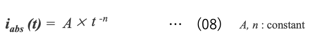
The rate at which a dipole responds to an external electric field is called the relaxation time. This relaxation time ranges from a few seconds to tens of seconds for electron-dependent dipoles and up to several hours for large molecular complexes. In other words, a current continues to flow in the dielectric depending on the relaxation time. This current, also called absorption current or polarization current, can be approximated by the time power function in equation (08)*13, *14, *15
*13 Takashi TETSUTANI et.al.
Relaxation Spectroscopy of the Dielectric Jl-Relaxation in Poly(n-alkyl methacrylate)s by Absorption-Current Measurements. II. Dielectric Relaxation Spectrum for Isotactic Poly(methyl methacrylate) , Polymer Journal, Vol. 14, No. 6, pp 471-476 (1982)
*14 Namika, et.al., J. Ceram. Assoc. Japan 76 [3] 1968
*15 Shiraishi et.al., IEEJ Transactions on Electrical and Electronic Engineering 86-1, No. 928, pp 75-84 (1966)
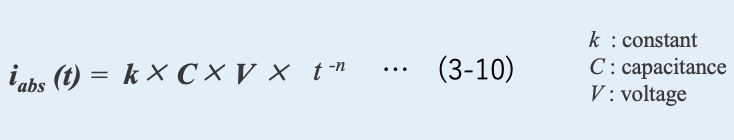
iabs (t) in equation (08) represents the absorbed current as a function of time, and A and n are constants that depend on temperature. For dielectrics used in ordinary capacitors, the value of n ranges from 0.3 to 1.2. The value of n for each capacitor can be obtained from the data in Figures 4b and 5, as shown in Table 1.

The absorption current iabs (t) is closely related to the dielectric loss ε"(f) of the dielectric. This relationship can be expressed using Hamon's approximation*15 as in equation (09).
*15 Shiraishi et.al., IEEJ Transactions on Electrical and Electronic Engineering 86-1, No. 928, pp 168-177 (1966)
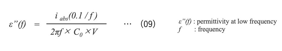
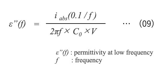
where f is the frequency, ε"(f) is the dielectric loss factor at frequency f (s-1 : inverse of time t), C0 is the capacitance, and V is the applied DC voltage. iabs(0.1 / f ) is the absorption current at t =0.1/ f [sec]. For example, ε" at f = 0.1 [c/s] can be calculated from the current value at t = 0.1/f = 1 [s] using equation (09).That is, the absorption current iabs (t) is used to polarize the dielectric and depends not only on time t but also on capacitance C and voltage V. From this, iabs (t) can be rewritten as the following approximate expression.
What is capacitor leakage current?
In Figure 5, a small capacitor, 0.022 μF 50V, began to have a time-independent steady current flow about 100 seconds (about 1.7 minutes) after the start of charging. This current is different from the charging current or absorption current, which inhibits charge accumulation and causes energy loss. This is called "leakage current ileak". However, leakage current has the following elements
- Inherent current caused by the conduction of electrons through the bulk of the dielectric layer.
- Current associated with structural or mechanical defects such as cracks or delamination in the dielectric.
- Current that bypasses between electrodes without going through the dielectric.
As mentioned in the previous section, to accurately measure pure leakage current that does not include absorption current, it is necessary to confirm that the measured current is the true leakage current by allowing sufficient time for charging. At room temperature and rated voltage, however, measurement can take many hours.
For this reason, the IEC standard specifies a charging time of 1 or 5 minutes for measuring leakage current, depending on the type of capacitor, and the MIL standard specifies 2 minutes or more.
Therefore, it should be noted that the leakage current indicated by the capacitor manufacturer is not the true leakage current, but the current including the absorption current.
Three components of DC current flowing through a capacitor
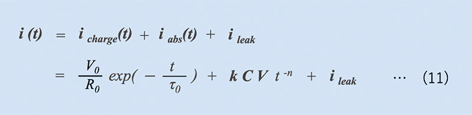
As mentioned above, the actual DC current flowing through a capacitor consists of three elements: charging current, absorption current, and leakage current. The role and characteristics of each element are summarized in Table 2.

*16 The three components are discussed in next section.
As shown in Figure 8, the DC current flowing through a capacitor varies with time. That is, when voltage is applied to the capacitor, a charging current flows instantaneously, accumulating charge on the electrodes. When the charge to the electrode ends and the charging current decays, an absorption current flows and dielectric polarization begins. When dielectric polarization ends, a leakage current appears.
Using equation(02) and (10), the DC current i(t) flowing through the capacitor can be expressed in a mathematical formula as shown in equation (11).

Schematic diagram of DC current flowing through capacitor
- The actual DC current flowing through a capacitor consists of three elements: charging current, absorption current, and leakage current.
- The "pure" leakage current is not only a current that is passing through the bulk of the dielectric layer, but also bypassing between electrodes without going through the dielectric.
- It should be noted that the leakage current indicated by the capacitor manufacturer is not the true leakage current, but the current including the absorption current.
Characteristics of Leakage Current
Voltage dependence(I-V characteristics)
The higher the applied voltage, the larger the leakage current, and the leakage current increases rapidly when the rated voltage is exceeded. Figure 9 shows the I-V characteristics of our aluminum electrolytic and film capacitors.
Normally, the I-V characteristics of a capacitor are expressed with a logarithmic scale for the current and a normal scale for the voltage (Figure 9), but it is possible to estimate a model of electronic conduction by plotting them in different coordinates.

Voltage versus Current
Current flow consideration
It has been confirmed that the current through the dielectric is related to the electron conduction injected by the metal electrode into the insulator*17, *18. There are various views on the model of electron conduction, but the Schottky emission, Poole-Frenkel, space-charge limited, etc. are typical mechanisms have been proposed.
Schottky coordinates*19, *20, *21 that plot current in logarithms and voltage in square roots, Poole-Frenkel coordinates*22, *23 that use the logarithm of current divided by voltage [ln(I/V)] and the square root of voltage (√V), or linearization in both logarithmic coordinates [ln(I) vs. ln(V)] *24, *25 are used to prove the model. The slope is then the parameter of the model.
Since these models include an Arrhenius-like temperature dependence characterized by the activation energy Ea, a more detailed examination of the I-V characteristics and their temperature dependence is necessary to clarify the conductive mechanism of the leakage current in the capacitor.
*17 H. Y. Lee, et al, IEEE Transactions on Components Hybrids and Manufacturing Technology, vol. 7, pp. 443-453, 1984.
*18 M. Dawber, et al, Reviews of Modern Physics, vol. 77, pp. 1083-1130, Oct 2005.
*19 J. H. Koh, et. al, Integrated Ferroelectrics, vol. 39, pp. 1361-1368, 2001.
*20 L. Pintilie, et. al, Physical Review B, vol. 75, Mar 2007.
*21 J. C. Shin, et. al, JOURNAL OF APPLIED PHYSICS, vol. 86, pp. 506-513, Jul 1999.
*22 E. Loh, et. al, Journal of Applied Physics, vol. 53, pp. 6229-6235, 1982.
*23 P. Zubko, et. al, Journal of applied physics, vol. 100, Dec 2006.
*24 L. C. Burton, Virginia Polytechnic Inst. and State Univ., Blacksburg, VA, ADA199113, 1998.
*25 F. D. Morrison, et al, Applied Physics Letters, vol. 86, Apr 2005.
Temperature dependence
The leakage current shows a positive temperature characteristic. The temperature dependence differs depending on the type of capacitor. The leakage current of film capacitors is more temperature sensitive than that of aluminum electrolytic capacitors, and the leakage current increases approximately 2 to 4 times when the temperature increases by 10 degrees Celsius(Fig. 10).

Leakage current versus temperature
Leakage current of aluminum electrolytic capacitors tends to increase more in the high temperature range than in the low temperature range.
Using the results in Figure 10, an Arrhenius plot of the leakage current is plotted, and the activation energy Ea of the leakage current is compared as shown in Figure 11.

Arrhenius plot of leakage current
Since the activation energy Ea of film capacitors is 3 to 4 times larger than that of aluminum electrolytic capacitors, so some care might be taken when using film capacitors at high temperatures*26 . Since the activation energy of aluminum electrolytic capacitors is not uniform across the temperature range, the conductive mechanism is considered to be different at low and high temperatures.
Leakage current varies with temperature and voltage. However, it is difficult to clearly define and predict the trend in actual capacitors. On the other hand, knowing the I-V characteristics and temperature characteristics of leakage current in advance is extremely important not only for capacitor selection, but also for circuit design and quality assurance. For this reason, we recommend that you contact the capacitor manufacturer for the temperature and voltage characteristics of the leakage current, if necessary.
*26 The activation energy of ceramic capacitors is reported to be 0.55 to 1.1 eV in the following literature Alexander Teverovsky, NASA Electronic Parts and Packaging (NEPP) Program, Screening Techniques for Ceramic Capacitors with Microcracks, Part II. Leakage and Absorption Currents and Voltages in Ceramic Capacitors 2013
dielectric absorption(DA)
When the capacitor is fully charged, an absorbing current flows for a long time and the dipoles in the dielectric form a dipole chain (Figure 7). When the capacitor is discharged, it takes a corresponding amount of time to restore the dipole chain to its original state. And most capacitors do not release all of their charged charge. Assume that the capacitor is charged, then momentarily short-circuited, and finally opened (Figure 12). When shorted, the charge on the electrodes is discharged and instantly dissipated, but the dipole chain remains aligned with the captured charge.
When the capacitor is opened, the alignment of the dipole chain begins to break down, again inducing a charge on the electrodes. This voltage is called dielectric absorption*27 . Dielectric absorption is observed not only in aluminum electrolytic and ceramic capacitors, but also in tantalum and film capacitors. Dielectric absorption depends mainly on the properties of the dielectric material itself, but can also be affected by the capacitor manufacturing process and electrode material.
*27 This is also called "recovery voltage". It's discussed in Chapter 1.

Charging and discharging of capacitor
The measurement of dielectric absorption (DA) is specified in MIL-PRF-1978 as follows (1) Charge the capacitor at rated voltage for 1 hour. (2) Discharge the capacitor for 10 seconds. (3) Measure the recurrent voltage with a voltmeter having an input resistance of 10,000 MΩ or more at the maximum voltage within 15 minutes. (4) Calculate the ratio of the maximum recurrence voltage to the charging voltage as DA.
Film capacitors made of polypropylene or polyphenylene sulfide show very small DA*28. On the other hand, ceramic capacitors*29, aluminum electrolytic capacitors, and tantalum capacitors with high dielectric constant show large values.
*29 X. Xu, et al. "Advances in Class-I C0G MLCC and SMD Film Capacitors," in The 28th symposium for passive components, CARTS'07, Newport Beach, CA, 2008.
High dielectric absorption can degrade accuracy and cause errors in analog circuits such as sample-and-hold circuits, analog-to-digital converters, and active filters*29. Dielectric absorption can also cause errors in voltage-to-frequency conversion circuits of voltage-controlled oscillators (VCOs) *29. Special compensation circuits have been applied to reduce the effects of dielectric absorption in some high-sensitivity, high-precision applications*30, *31. Table 3 summarizes the DA of major capacitors.
*30 J. C. Kuenen and G. C. M. Meijer, "Measurement of dielectric absorption of capacitors and analysis of its effects on VCOs," Instrumentation and Measurement, IEEE Transactions on, vol. 45, pp. 89-97, 1996.
*31 C. Iorga, "Compartmental analysis of dielectric absorption in capacitors," Dielectrics and Electrical Insulation, IEEE Transactions on, vol. 7, pp. 187-192, 2000.
 of various capacitors")
Leakage current and self-healing
Defective areas or spots in the dielectric can cause leakage current. However, when a charging current rushes into that area, the current energy makes repair or intercept that area and the electrode layer, returning it to a normal state. This is called self-healing. However, this healing mechanism varies from capacitor to capacitor. This section outlines self-healing in metalized film capacitors, aluminum and tantalum capacitors.
Metalized film capacitor
Self-healing is frequently observed in evaporated-electrode film capacitors. These capacitors contain defects in the film and mechanical damage from the manufacturing process. When a voltage is applied to the film capacitor, current is concentrated in these defective spots and a localized arc is generated.
The energy of the arc evaporates a small area of the deposited metal layer around the defect, physically separating the defect from the low insulation (Figure 13). The capacitor thus returns to its electrically normal state, and the leakage current originating from the defect is reduced*32. However, if self-healing occurs frequently, the capacitance will decrease*33, *34.

Self-healing at metalized film capacitor
*32 The magnitude of this energy is not enough to break down or carbonize the film.
*33 J.H. Tortai, N. Bonifaci, A. Denat, C. Trassy, Diagnostic of the Self-healing of Metallized Polypropylene Film by Modeling of the Broadening Emission Lines of Aluminum Emitted by Plasma Discharge, J. Appl. Phys. (2005), pp.053304.
*34 G. Picci, M. Rabuffi, Status Quo and Future Prospects for Metallized Polypropylene Energy Storage Capacitors, Ieee T. Plasma Sci. (2002), pp.939-1942
Polymer cathode aluminum, and tantalum capacitor
In aluminum electrolytic and tantalum capacitors using conductive polymers as the cathode, when current flows through a defective spot in the dielectric, Joule heat is generated and the defective spot is heated to about several hundred degrees Celsius. As a result, the conductive polymer loses its conductivity and becomes insulating, blocking the current to the defective spot. *35, *36

Self-healing of Polymer cathode aluminum, and tantalum capacitor
*36 15K.S. Jang, B. Moon, E.J. Oh, H. Lee, Characteristics of tantalum electrolytic capacitors using soluble polypyrrole electrolyte, J. Power Sources (2003), pp. 338-442
Electrolyte cathode aluminum capacitor
Self-healing of aluminum electrolytic capacitors, electrolyte cathode, is a process in which defective spots are electrochemically repaired by ions in the electrolyte. In other words, the defective spot is anodized and remolded into a new dielectric*37. In the manufacturing process of this capacitor, there is a process that uses self-healing to stabilize the leakage current*38 .
*37 This process is also called "reformation" or "aging".
*38 In this process, a DC voltage greater than the rated voltage but less than the anodizing voltage is applied to the capacitor at the rated temperature. Appropriate re-generating reduces the probability of infant mortals.
Self-healing has the effect of reducing the leakage current of the capacitor. The mechanism, however, depends on the type of capacitor (Table 4). Although self-healing is essential to improve capacitor reliability, it should be noted that self-healing may not function under conditions such as a defect spot that is too large to repair, high temperatures exceeding the maximum operating temperature, overvoltage, or high currents.
 features by capacitor type")
- Leakage current increases at high temperatures and high voltages.
- Since the behavior and changes in leakage current vary depending on the type of capacitor, it is extremely important to understand the trend in advance.
- The higher the capacitance of a capacitor, the greater the dielectric absorption, so care must be taken when using it.
- Self-healing reduces leakage current.
- However, self-healing has different mechanisms depending on the type of capacitor and may not work under harsh conditions.
Leakage Current of Aluminum Electrolytic Capacitors
Aluminum electrolytic capacitors are critical components that have a significant impact on the performance of desiccant and power electronic equipment. In these applications, the characteristics of aluminum electrolytic capacitors directly affect the life and reliability of the equipment. This section focuses on the leakage current of aluminum electrolytic capacitors, providing an overview of the technology, characteristics of leakage current, and reliability.
Dielectric of aluminum electrolytic capacitor
The aluminum oxide dielectric formed on the surface of the anode is in almost complete contact with the electrolyte of the cathode (Figure 15). The dielectric is formed as an ultrathin film on the aluminum surface by an electrochemical process called anodic oxidation or anodization. The dielectric not only affects capacitance, but also has a significant impact on withstand voltage and leakage current characteristics, which directly affects the reliability of aluminum electrolytic capacitors. The anodic oxide layer of aluminum can be roughly classified into a porous type produced in an acidic (or basic) solution and a barrier type produced in a neutral electrolyte bath, the latter being used in aluminum electrolytic capacitors*39 .
*39 Barrier-type layers are thinner than porous one and are used for aluminum electrolytic capacitors and insulating substrates, taking advantage of their electrical properties such as dielectric and insulation properties.

Element structure of aluminum electrolytic capacitor
Figure 16 shows a cross-sectional schematic of the dielectric layers. A layer of amorphous aluminum oxide directly contact to aluminum foil anode, followed by a layer of crystalline aluminum oxide, with a layer of hydrated oxide (aluminum hydroxide) on the top surface*40, *41, *42

A cross-sectional schematic of the dielectric layers
*40 The formation of aluminum oxide involves multiple steps of hydration, anodization, heat treatment, and phosphating, and this process is believed to create the structure shown in Figure 15.
*41 Tanaka, et.al., Journal of the Surface Finishing Society of Japan, 69, (12) pp542- 543, (2018)
*42 Sining Pan et.al, "Microstructure evolution for oxide film of anodic aluminum foil used in high voltage electrolytic capacitor ".Journal of Alloys and Compounds Volume 823, 15 May 2020, 153795
Amorphous layers do not have the translational symmetry of crystals, and molecules are loosely bound to each other with little interaction. This feature results in less heat generation due to fluctuations in the electric field caused by alternating current. Molecules in the crystalline layer are more densely arranged and strongly bonded, resulting in high insulation resistance and low leakage current. Molecules in the hydration layer are easily polarized and generate relatively large losses. At high temperatures, water molecules dissociate from the hydration layer and the layer becomes brittle, which is thought to increase leakage current. Therefore, in order to create a good quality dielectric layer, it is important to stabilize the hydration layer and to use technology to thicken the amorphous and crystalline layers. We have excellent features in anode foil and dielectric formation technology.
Leakage current, its specification and actual values
We apply the standard in accordance with JIS C 5101-4:2019 (IEC 60384-4:2016). Table 5 shows an example of the specified values of leakage current for our aluminum electrolytic capacitors.

Leakage current is measured after 5 minutes of applying the rated voltage at 20°C. However, for capacitors with large capacitance or high rated voltage, the leakage current is not constant because the absorption current continues to flow even after 5 minutes. In other words, the specified value of leakage current is not the pure leakage current, but the value including the absorbed current.
In principle, the standard value of leakage current is obtained by multiplying the product of capacitance and voltage by a coefficient. This coefficient can be thought of as the constant k in equation (11), with the unit being μA /(μF x V). Leakage current, which are industrial products, varies widely. For this reason, the standard value of leakage current is set with a margin to the actual value in consideration of economic efficiency. The margin varies depending on the type of capacitor, but is generally 1/10 to 1/100 of the specified value.
notification
The main cause of leakage current in aluminum electrolytic capacitors is dielectric defects. However, defects can be caused by a variety of factors, including manufacturing damage (e.g., foil cutting, tab crimp connections), various lattice defects in the crystal, the presence of dissimilar atoms in the aluminum substrate layer, mechanical stress, and partial dissolution of the oxide film into the electrolytic solution. As shown in Figure 4b, the current flowing through an aluminum electrolytic capacitor when charged decreases almost exponentially immediately after the application of voltage, and after dielectric absorption, a leakage current of almost constant value finally appears. If the capacitor is manufactured by a controlled process, the effects of bypass current*43 and tunneling effect*44 on the leakage current can be ignored. As mentioned above, the leakage current of aluminum electrolytic capacitors depends on time, magnitude of applied voltage, and temperature, but there are additional considerations that must be taken into account when using these capacitors.
*43 This is a current that does not pass through the dielectric but bypasses between the electrode terminals.
*44 It is a phenomenon in which an electron passes through the dielectric insulating potential (potential energy) of a dielectric.
Reverse voltage
Since aluminum electrolytic capacitors are polarized, reverse voltage must not be applied. When a reverse voltage is applied, i.e., a forward voltage to the cathode of the electrolyte and a negative voltage to the dielectric layer, hydrogen ions collected in the dielectric layer pass through the layer as proton current, reach the boundary between the layer and the metal layer, and are converted to hydrogen gas (Figure 17). The expansion force of this hydrogen gas causes the dielectric layer to peel off, and after the electrolyte decomposes, a current flows through the capacitor and the capacitor fails*45. Therefore, when a reverse voltage is applied, a large leakage current continues to flow, gas is generated inside the capacitor, pressure rises, and the pressure relief vent may open and fail (Figure 18).
*45 The mechanism of applying reverse voltage to aluminum electrolytic capacitors has been reported in many papers. The following paper is a review.
J. W. Diggle, Thomas C. Downie, and C. W. Goulding, Chem. Rev., 1969, 69 (3), 365-405

A cross-section of capacitor element

Opened vent due to reverse voltage
アThe reverse voltage allowed by aluminum electrolytic capacitors is very small, only a few volts for those with electrolyte. jis c 5101-4:2019 (IEC 60384-4:2016) The reverse voltage test condition specified in JIS C 5101-4:2019 (IEC 60384-4:2016) is 1 V at the upper category temperature (Condition A; test duration 125 hours).*46
*46 The reverse voltage of conductive polymer type capacitors without electrolyte is 0.15 times the rated voltage
Storage
When aluminum electrolytic capacitors are stored for a long period of time without a load (without applying DC voltage), the leakage current increases. The higher the storage temperature, the more pronounced this phenomenon becomes. Therefore, care should be taken when using aluminum electrolytic capacitors that have been stored for a long time as maintenance parts.
")
Storage(image)
This is said to be because the high temperature degrades the insulating property of the oxide film of the dielectric*47. The same thing also happens to capacitors that have been transported for a long period of time, even if they have just been delivered from the manufacturer. Low-voltage capacitors using organic solvent electrolytes (rated voltage up to 100V) are relatively stable, but high-voltage capacitors using ethylene glycol electrolytes (rated voltage from 160V), especially capacitors of so-called "low ESR specifications" using water-based electrolytes, may show increased leakage current. Unless otherwise specified, our aluminum electrolytic capacitors are not suitable for this purpose. Unless otherwise specified, our aluminum electrolytic capacitors can be stored without voltage for 3 years at temperatures from +5 °C to+35 °C and relative humidity below 75%*48 . Within this period, the capacitors can be used at their rated voltage without modification after they are removed from storage. Figure 20 shows the results of a study of changes in leakage current after long-term storage of our screw terminal type aluminum electrolytic capacitors. The leakage current increased by a factor of 2 to 3 regardless of the type and rating of the capacitor.
*47 Some reports state that dielectric films dissolve to some extent depending on temperature and electrolyte composition, but that oxide films do not regenerate (self-heal) unless voltage is applied. Thiesbürger, K.H., Der Elektrolytkondensator, Roederstein, Landshut (1991)
*48 For capacitors that are soldered to the board, the capacitors must be mounted within 2 years to prevent soldering problems.

Leakage current change of aluminum capacitor at initial and after 3-years storage
Capacitor bank and voltage blancing
In AC drive systems (Figure 21), welding converters, and switching-mode power supplies for telecommunications equipment, the DC voltage link between converter and inverter is connected to a 400/500 V three-phase supply. In these applications, two aluminum electrolytic capacitors may be placed in series together with a voltage divider resistor. The reason for the series connection is that the DC link voltage level of the converter is typically 500-800 V, while the maximum voltage rating of the aluminum electrolytic capacitors is only 500-600 V, making it difficult to design with a single capacitor.

AC drive system with two electrolytic capacitors connected in series.
Circuit topology of a three-phase power converter
In a series connection of capacitors, the voltage across the individual capacitors is divided according to the ratio of the capacitor's insulation resistance (or the ratio of the capacitor's leakage current)*49. However, if the divided voltages are unequally balanced, the overall efficiency of the equipment will be reduced and the life of the capacitors will be shortened *50. For this reason, it is important to divide the voltage evenly.
It is necessary to optimize the resistance of the voltage divider resistor or to design the current through the resistor so that it exceeds several times the leakage current, and technologies to solve these problems have been reported in recent years (Figure 22)*51.
*49 CLC/TR 50454:2008, Guide for the application of aluminium electrolytic capacitors, CENELEC, Brüssel (2008)
*50 When converters are constantly connected to the main power supply, as in industrial equipment, the losses due to the voltage divider resistors cannot be ignored in terms of energy and cost. In addition, the voltage divider resistors are often installed close to the capacitors as a heat source, posing a risk to the capacitors and other de-energizers.

Stabilizes the midpoint voltage UMid and improves power dissipation Improved voltage balancing circuit*51
*51 H. Ertl et al, "Active voltage balancing of DC-link electrolytic capacitors" https://www.pes-publications.ee.ethz.ch/uploads/tx_ethpublications/ertl_IET-PE_2008_.pdf
Since the leakage current of aluminum electrolytic capacitors varies depending on operating conditions and long-term use, it is effective to reduce the deviation of leakage current of capacitors connected in series by combining capacitors of the same production lot or using capacitors with low leakage current specifications.*52
*52 Since aluminum electrolytic capacitors have a capacitance tolerance of ±20% and voltage sharing is performed according to the capacitance deviation in the initial stage of charging, consideration must also be given to capacitance in series connection.
Leakage Current Summary
[Leakage Current]
- Leakage current inhibit the accumulation of electric charge and cause energy loss.
- The magnitude of leakage current is affected by dielectric composition and defects, time, voltage, and temperature.
- Under normal conditions (normal temperature and short charge time), the leakage current is observed as a combined current with the absorption current.
[Leakage Current of Aluminum Capacitor]
- Since it is highly dependent on the physical properties of the oxide film that is the dielectric, the leakage current can be optimized by properly controlling the process of forming the dielectric.
- If a reverse voltage is applied, a large leakage current will continue to flow, leading to failure. Leakage current also increases when voltage is left unapplied.
- Since there is variation in leakage current, care must be taken when using series connection.
The model and applicability of the leakage current described in this chapter vary depending on the conditions of use, type of product, and application. Therefore, in applications where the magnitude of the leakage current greatly affects the performance of the equipment, counseling by the capacitor manufacturer is recommended.
CONCLUTION
Capacitors come in a variety of types and characteristics depending on the dielectric, and are essential devices used in both digital and analog circuits.
The unique properties and performance of each capacitor, such as operating voltage, capacitance, dissipation and frequency response, leakage current, device size, and frequency response, allow customers to select the best capacitor for their application.
However, a real capacitor is not an ideal component with capacitance alone. There are parasitic resistors and inductances in series with the capacitance, as well as resistors in parallel with the capacitance. These can cause losses.
For this reason, this report describes the most basic and important characteristics of capacitor performance: capacitance, impedance, and leakage current.
We continues to improve its dielectric performance, capacitor construction, and manufacturing technology to provide compact, low-loss, and highly reliable products. At the same time, we ask our customers to properly select capacitors with quality and reliability that meet the requirements of their applications, to take safety design and safety measures, and to conduct thorough evaluations in advance.
We hope that this report will be of help to you in selecting the right capacitors, improving the functionality of your application, and maintaining your capacitors.
Thank you for taking your time to read this report. If you have any questions, please do not hesitate to contact us.

Editorial supervision/Kazuyuki Iida
General Advisor, AIC tech Inc.
Born in the Tokyo area in 1956
M.S. of Sc, Sophia University, Tokyo, Japan. 1982
Over 35 years experience with knowledge on capacitor technology, i.e. R&D for high-performance capacitor and its materials, marketing activities at Hitachi Chemical Co, Ltd. and Hitachi AIC Inc. and Contributed articles on capacitors to public relations magazines, trade journals, and various handbooks.
Instructor of capacitor technology at the Technical Training Institute of Hitachi, Ltd. from 2005 to 2015.
General advisor to AIC tech Inc. from 2020.
- "Tantalum Electrolytic Capacitor"
The Electrochemical Society of Japan (ed.) Maruzen Handbook of Electrochemistry, 5th Edition, Chapter 15, Capacitors, Section 15.2.4 b (1998) - "Development Trend and Material Technology of Tantalum-Niobium Capacitors"
Technical Information Association of Japan Seminar June 2008 - Lead-Free Surface Mount Film Capacitors MMX-EC, MML-EC Series
Hitachi Chemical Technical ReportNo. 48. Product Introduction 2007 - "Film Capacitors for Electronic Devices"
Maruzen Capacitor Handbook, 5th Edition, Chapter 5, Film Capacitors, Section 5.2 (2009). - "Film capacitor MLC series for new energy"
Shinkobe Electric Co., Ltd. Shinkobe Technical Report Np. 22 (2012).
PDF Download